35. PLC Commissioning Checklist ( 35 of 35 )
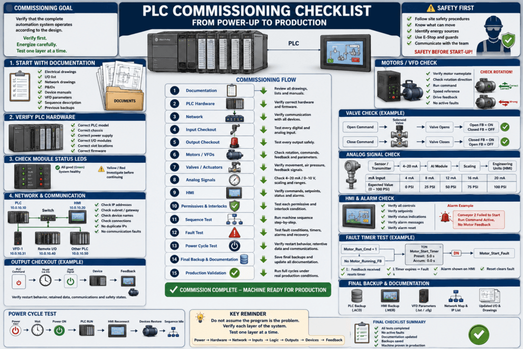
Commissioning is the stage where a PLC control system moves from programmed to proven in the real machine.
A program may look correct offline and still fail during startup because commissioning involves much more than ladder logic.
You must verify:
- Electrical installation
- PLC hardware
- Network communication
- Inputs
- Outputs
- Motors and VFDs
- Valves and actuators
- Analog signals
- HMI operation
- Safety systems
- Machine sequences
- Faults and alarms
- Documentation and backups
A good automation technician does not simply download the PLC program and press Start.
Commissioning should be performed systematically.
Verify first. Energize carefully. Test one layer at a time.
1. What Is PLC Commissioning?
PLC commissioning is the process of verifying that the complete automation system operates according to the design.
The PLC is only one part of that system.
A typical automated machine includes:
Power Distribution
        ↓
PLC
        ↓
Input Modules
        ↓
Sensors
        ↓
Control Logic
        ↓
Output Modules
        ↓
Motors / VFDs / Valves
        ↓
Feedback
        ↓
HMI / Alarms
Commissioning confirms that every part of this chain works correctly.
2. Commissioning Is Different From Programming
Programming answers:
What should the machine do?
Commissioning answers:
Does the real machine actually do it?
For example, the PLC may contain:
Valve_Open_Cmdbut during commissioning you must verify:
PLC Command
      ↓
Output Module
      ↓
Terminal
      ↓
Solenoid
      ↓
Air Supply
      ↓
Valve Moves
      ↓
Valve_Open_FB
If any link fails, the machine may not operate correctly even though the program is perfect.
3. Safety Comes Before Commissioning
Before energizing equipment, follow the site’s approved electrical and machine-safety procedures.
Commissioning may involve:
480 VAC
240 VAC
120 VAC
24 VDC
Pneumatics
Hydraulics
Motors
Conveyors
Robots
Moving machinery
Stored mechanical energy
Before testing motion, confirm that personnel understand:
- What equipment may move
- Which areas are restricted
- Where the emergency stops are
- Who is controlling the machine
- What energy sources are present
Never assume equipment is safe simply because the PLC is in Program Mode.
4. Start With Documentation
Before testing anything, collect the available documentation.
Useful documents include:
Electrical drawings
PLC program
I/O list
Network drawings
P&IDs
Device manuals
VFD parameter sheets
Motor nameplates
Instrument ranges
Machine sequence description
Safety drawings
Previous backups
These documents become your commissioning reference.
Without documentation, troubleshooting becomes slower and more dependent on guessing.
5. Verify the PLC Hardware
Before downloading a program, inspect the controller hardware.
Check:
Correct PLC model
Correct chassis
Correct power supply
Correct I/O modules
Correct slot locations
Correct firmware
Correct communication modules
Correct network adapters
Example:
The project expects:
Slot 0 — Controller
Slot 1 — Digital Input
Slot 2 — Digital Output
Slot 3 — Analog Input
Slot 4 — Ethernet Module
If the real chassis is different, the controller may report module connection faults.
6. Check Module Status LEDs
Before troubleshooting software, inspect the hardware indicators.
Depending on the system, look for LEDs such as:
OK
RUN
FLT
I/O
NET
LINK
MOD
NS
MS
A healthy PLC system should normally show the expected healthy-state indicators.
A flashing or red LED may indicate:
Module fault
Communication failure
Configuration mismatch
Network problem
Missing module
Wrong firmware
Field wiring problem
The LEDs can provide valuable information before you even go online.
7. Verify the PLC Program Before Download
Before downloading, confirm that you have the correct project.
Check:
Machine name
Controller name
PLC model
Firmware revision
Project revision
Last modified date
Program version
Do not assume a file named:
Machine_Final.ACDis actually the latest version.
Version control matters.
8. Make a Backup Before Changes
If the machine already contains a PLC program, upload and save a backup before downloading anything.
A good naming method might be:
Wrapper01_Before_Commissioning_2026-08-15.ACDor:
Filler_Line2_PreChange_Rev03.ACDThe exact format is less important than having a clear, traceable backup.
You should be able to answer:
What program was there before?

What program was downloaded?

Who made the change?

When was it changed?
9. Verify Network Configuration
Modern PLC systems depend heavily on industrial networks.
Check:
PLC IP address
HMI IP address
VFD IP addresses
Remote I/O IP addresses
Subnet mask
Gateway
Managed switch configuration
Device names
EtherNet/IP connections
Example:
PLC           10.0.10.10
HMI           10.0.10.20
VFD-1         10.0.10.31
Remote I/O    10.0.10.40
Check for:
Duplicate IP addresses
Wrong subnet
Incorrect device configuration
Disconnected cables
Bad ports
Wrong switch VLAN
Communication faults
10. Verify Communication Before Machine Operation
Before testing machine motion, confirm that the PLC communicates with all required devices.
Examples:
HMI ↔ PLC
PLC ↔ Remote I/O
PLC ↔ VFD
PLC ↔ Other PLC
PLC ↔ Instrument
PLC ↔ Robot
In Studio 5000, inspect the I/O tree.
Look for:
Yellow warning symbols
Connection faults
Module inhibited
Incorrect module definitions
Communication errors
A machine should not be commissioned while major communication faults are being ignored.
11. Perform an I/O Check
One of the most important commissioning tasks is the I/O checkout.
Do not assume the drawings match the field wiring.
Every important input and output should be verified.
12. Digital Input Checkout
For each digital input:
- Identify the field device.
- Activate the device physically.
- Observe the input module LED.
- Verify the raw PLC input.
- Verify the internal buffered tag.
- Verify the HMI indication if applicable.
Example:
Photoeye blocked
       ↓
Input module LED ON
       ↓
Local:2:I.Data.3 = 1
       ↓
DI_Box_Present = 1
       ↓
HMI shows Box Present
If any stage disagrees, investigate before continuing.
13. Verify Input Logic State
A sensor being electrically active does not always mean the PLC logic should show TRUE.
You must understand whether the device is:
Normally Open
Normally Closed
PNP
NPN
Active High
Active Low
Fail-safe wired
Example:
A normally closed safety-related status contact may be healthy when electrically energized.
So:
Input ON = Healthy
Input OFF = Fault
Understanding signal polarity is critical during commissioning.
14. Digital Output Checkout
Outputs require more caution because they may create motion.
For each output:
Verify the destination
Confirm the machine is safe
Activate the output through normal logic when possible
Observe the PLC output
Observe the module LED
Measure the field signal if necessary
Verify device operation
Verify feedback
Example:
Valve_Open_Cmd
       ↓
DO_Valve_Open
       ↓
Output module
       ↓
Solenoid energized
       ↓
Valve opens
       ↓
Valve_Open_FB
Do not stop at:
The PLC output is ON.
The physical device must actually operate correctly.
15. Avoid Blind Forcing
Forcing can be useful during commissioning, but it can also be dangerous.
A forced output may bypass:
Permissives
Interlocks
Sequence logic
Machine modes
Normal stopping conditions
Before forcing anything, understand:
What will move?

What devices depend on this output?

Could another machine start?

Could product or pressure be released?

Can the force be safely removed?
Whenever possible, test outputs through properly controlled manual or maintenance logic instead.
16. Verify Motor Rotation
Motor direction must be confirmed during commissioning.
A motor running backward can cause:
Pump damage
Conveyor jams
Reverse product flow
Mechanical damage
Incorrect fan airflow
Equipment failure
For a motor or VFD:
Jog briefly
Verify direction
Stop
Correct wiring or configuration if required
Retest
Do not allow a motor to operate for an extended period before confirming rotation.
17. Verify VFD Configuration
A VFD requires more than a run command.
Confirm important parameters such as:
Motor voltage
Motor current
Motor frequency
Motor RPM
Motor power
Acceleration time
Deceleration time
Minimum frequency
Maximum frequency
Command source
Speed reference source
Network configuration
Overload settings
Compare the VFD setup to the motor nameplate and machine requirements.
18. Verify VFD Command and Feedback
A typical VFD control path may be:
PLC_Run_Cmd
      ↓
VFD Run Command
      ↓
Drive Running
      ↓
Motor Running
      ↓
VFD Running Feedback
      ↓
PLC
Also verify:
Drive Ready
Drive Faulted
Actual Frequency
Actual Current
Speed Reference
Fault Code
Command and feedback should never be assumed to be the same thing.
19. Check Valves and Pneumatics
For pneumatic valves, verify:
Air pressure
Regulator setting
Solenoid operation
Valve movement
Open limit switch
Closed limit switch
Tubing connections
Flow controls
Mechanical binding
A PLC output may energize correctly while the valve still fails because:
No air pressure
Bad solenoid
Blocked tubing
Incorrect plumbing
Mechanical failure
Missing feedback sensor
20. Test Valve Feedback
For a double-position valve:
Open Command
      ↓
Valve Moves
      ↓
Open Feedback = ON
Closed Feedback = OFF
Then:
Close Command
      ↓
Valve Moves
      ↓
Closed Feedback = ON
Open Feedback = OFF
If both feedbacks are active simultaneously when they should not be, investigate:
Sensor adjustment
Mechanical position
Wiring
PLC logic
Wrong input assignment
21. Verify Analog Inputs
Analog devices require careful commissioning.
Typical signals include:
4–20 mA
0–10 VDC
RTD
Thermocouple
Load cell
Pressure transmitter
Level transmitter
Flow meter
Verify the entire signal chain:
Process Value
      ↓
Sensor / Transmitter
      ↓
Electrical Signal
      ↓
Analog Input Module
      ↓
Raw PLC Value
      ↓
Scaling
      ↓
Engineering Units
      ↓
HMI
22. Check Analog Scaling
Suppose a pressure transmitter is:
4 mA  = 0 PSI
20 mA = 100 PSI
At approximately:
12 mAthe PLC should display approximately:
50 PSIIf the transmitter shows 50 PSI but the HMI shows 25 PSI, the problem may be scaling rather than the sensor.
Always verify:
Instrument range
PLC module configuration
Raw signal
Scaling
Engineering units
HMI display
23. Verify Analog Outputs
Analog outputs may control:
VFD speed
Control valves
Pressure regulators
Positioners
Heaters
Process setpoints
Example:
0% command
      ↓
4 mA

50% command
      ↓
12 mA

100% command
      ↓
20 mA
Verify the output at several points, not only at one value.
24. Verify HMI Operation
The HMI should be commissioned along with the PLC.
Check:
Start buttons
Stop buttons
Mode selection
Setpoints
Status indicators
Alarm screens
Navigation
User security
Trend displays
Manual controls
Reset buttons
A button should not merely change appearance.
Verify the PLC actually receives the command.
25. Verify HMI Commands From the PLC Side
Example:
Press:
HMI Conveyor StartThen verify:
HMI_Conveyor_Start = 1inside the PLC.
Then follow:
HMI_Conveyor_Start
       ↓
Conveyor_Start_Request
       ↓
Conveyor_Run_Permissive
       ↓
Conveyor_Run_Cmd
This confirms that the HMI-to-PLC signal path works correctly.
26. Verify HMI Status From Real Feedback
Good HMI status should usually represent actual machine condition.
For example:
Prefer:
Motor_Running_FBfor a Motor Running indicator instead of simply using:
Motor_Run_Cmdbecause:
Command ONdoes not guarantee:
Motor actually runningThe same applies to valves, conveyors, pumps, and other equipment.
27. Test Permissives
Before testing automatic operation, verify each important permissive individually.
For example:
Auto_Mode
Guard_OK
Air_Pressure_OK
VFD_Ready
No_Fault
Product_Available
Downstream_Ready
Remove one condition at a time and confirm that the PLC blocks operation correctly.
A permissive that is never tested may fail exactly when it is needed.
28. Test Interlocks
Interlocks should also be validated.
Example:
If Valve A and Valve B must never open simultaneously:
Valve_A_Open
       ↓
Valve_B_Open should be blocked
Test the condition deliberately under controlled commissioning conditions.
Do not assume an interlock works just because the rung looks correct.
29. Verify the Machine Sequence
Once individual devices work correctly, begin testing the machine sequence.
Do not start with full production speed.
Run the process slowly or step-by-step when possible.
Example:
Idle
 ↓
Box Detected
 ↓
Conveyor Stops
 ↓
Valve Opens
 ↓
Filling
 ↓
Target Reached
 ↓
Valve Closes
 ↓
Conveyor Restarts
At each step ask:
Did the correct action occur?

Did the required feedback arrive?

Did the sequence move to the next state?

Was anything unexpected activated?
30. Test Sequence Transitions
Every state should have a clearly verified transition.
Example:
State 20 — Waiting for Box

Box_Present = TRUE
        ↓
State 30 — Filling
Then verify:
State 30 — Filling

Target_Weight_Reached = TRUE
        ↓
State 40 — Fill Complete
If the machine becomes stuck, determine which transition condition is missing.
31. Test Fault Conditions Intentionally
Commissioning should validate not only normal operation but also failure handling.
Typical tests include:
Motor does not start
Valve fails to open
Valve fails to close
Sensor remains blocked
Feedback disappears
VFD faults
Communication drops
Filling takes too long
Tank reaches high level
The purpose is to verify that the PLC responds correctly.
32. Test Fault Timers
Suppose a motor is commanded to start.
Expected logic:
Motor_Run_Cmd
+
No Motor_Running_FB
        ↓
TON Motor_Start_Timer
        ↓
Motor_Start_Fault
During commissioning, verify:
- Motor command starts the timer.
- Correct feedback resets the timer.
- Missing feedback eventually creates the fault.
- The fault produces the correct machine response.
- The HMI shows the correct alarm.
- Reset behavior works correctly.
33. Verify Alarm Messages
An alarm should tell the technician something useful.
Poor alarm:
FAULT 23Better alarm:
Conveyor 2 Failed to StartEven better:
Conveyor 2 Failed to Start — Run Command Active, No Motor FeedbackDuring commissioning, confirm:
Correct alarm appears
Correct equipment is identified
Alarm clears appropriately
Acknowledgement works
Latched alarms reset correctly
34. Test Loss of Communication
Communication failures should also be considered.
For critical systems, verify what happens if communication is lost between:
PLC and HMI
PLC and VFD
PLC and Remote I/O
PLC and another PLC
PLC and robot
Ask:
Does the machine stop safely?

Does the output remain in the last state?

Does it turn off?

Does the PLC generate a fault?

Does the HMI show communication loss?
Fail-safe behavior should be understood before production.
35. Test Power Cycle Behavior
One of the most important commissioning tests is a controlled power cycle.
Verify what happens when the machine is shut down and restarted.
Questions include:
Does the PLC return to RUN mode?

Does the HMI reconnect?

Do remote I/O modules reconnect?

Do VFDs reconnect?

Do faults remain latched?

Does the machine unexpectedly restart?

Are sequence states retained?

Are critical values retained correctly?
Never assume restart behavior is correct.
Test it.
36. Verify Retentive Data
Some PLC values survive a power cycle.
Examples may include:
Setpoints
Production counters
Machine settings
Recipe values
Calibration values
Maintenance totals
Latched states
Determine which values should be retained and which should reset.
For example:
Production Totalmay need to remain.
But:
Motor_Start_Requestprobably should not automatically remain active after startup.
37. Verify Emergency Stop Recovery
E-stop circuits must be validated according to approved safety procedures.
Typical questions include:
Does motion stop as designed?

Are hazardous outputs removed?

Does the PLC detect the E-stop condition?

Does the HMI show the correct message?

Can the machine restart automatically?

Is manual reset required?
A machine should not unexpectedly resume motion simply because the E-stop was released.
38. Verify Guard and Safety Device Behavior
Commissioning may also include validation of:
Guard switches
Safety gates
Light curtains
Safety mats
Safety relays
Safety PLC inputs
Safety validation should follow the machine’s approved safety procedure and risk assessment.
Standard PLC logic should never be used as a substitute for required safety-rated functions.
39. Perform Dry Cycle Testing
Before introducing product, perform dry cycles when practical.
Dry cycling allows you to test:
Sensors
Sequence timing
Motor operation
Valve operation
Robot motion
Interlocks
Machine synchronization
without adding process material.
This reduces the risk of:
Product spills
Damaged containers
Contamination
Blocked equipment
Wasted material
40. Introduce Product Gradually
After successful dry testing, begin testing with actual product or load.
Start with controlled conditions.
Observe:
Real timing
Real motor load
Actual pressure
Actual weight
Actual flow
Sensor behavior
Process variation
A sequence that works perfectly without product may behave differently under real process conditions.
41. Monitor Timers During Real Operation
During production testing, watch important timers.
For example:
Valve_Open_Timer
Motor_Start_Timer
Fill_Timeout
Conveyor_Jam_Timer
Auto_Close_Timer
Communication_Timeout
If normal operation frequently approaches the preset value, the timing may need engineering review.
Do not simply increase timers to hide a mechanical or process problem.
42. Trend Important Analog Values
If available, use HMI trends or diagnostic tools to observe values such as:
Pressure
Flow
Weight
Temperature
Speed
Motor current
Level
PID output
Trending can reveal problems that are difficult to see from one instantaneous value.
For example:
Pressure oscillation
Weight instability
Motor overload
Noisy analog signal
Poor PID response
43. Watch the Machine, Not Only the Laptop
During commissioning, one of the easiest mistakes is becoming too focused on the PLC screen.
The PLC may say:
Valve_Open_FB = TRUEbut physically the valve could be:
Partially open
Mechanically jammed
Incorrectly installed
Opening the wrong line
Always compare:
PLC
+
Electrical signal
+
Physical machine behavior
44. Document Every Change
If you modify something during commissioning, document it.
Examples:
Timer changed from 3 s to 5 s
Photoeye debounce added
VFD acceleration changed
Analog scaling corrected
Input polarity corrected
HMI alarm text changed
Sequence transition corrected
Do not rely on memory.
Commissioning often includes many small changes that become important later.
45. Update Electrical and I/O Documentation
If field wiring differs from the original drawing, document the difference.
For example:
Drawing:

Local:2:I.Data.4 = PE_Box

Actual:

Local:2:I.Data.5 = PE_Box
Leaving documentation incorrect creates future troubleshooting problems.
Update:
I/O lists
Electrical drawings
Network maps
VFD parameter sheets
Device addresses
PLC comments
according to your facility’s document-control procedure.
46. Create a Final PLC Backup
After commissioning is complete, create a final verified backup.
Example:
Filler01_Commissioned_2026-08-15_Rev05.ACDThe final backup should match the program actually running in the controller.
Where appropriate, also save:
HMI application
VFD parameters
Robot backup
Network switch configuration
Instrument settings
Servo configuration
A PLC backup alone may not be enough to restore a modern automated machine.
47. Record the Final Firmware and Software Versions
Document important versions such as:
PLC firmware
Studio 5000 version
HMI firmware
FactoryTalk View version
VFD firmware
Robot software
Managed switch firmware
This information becomes extremely useful if the equipment must be restored years later.
48. Final Production Validation
Before commissioning is considered complete, observe the machine under normal production conditions.
Verify:
Several complete cycles
Normal production speed
Multiple product conditions
Correct alarms
Correct operator controls
Stable communications
No unexpected faults
Correct machine recovery
One successful cycle is not enough.
You want confidence that the system is stable.
Practical PLC Commissioning Checklist
Before Power-Up
- Verify electrical drawings.
- Verify PLC and I/O hardware.
- Confirm correct voltage levels.
- Check wiring and terminal connections.
- Verify grounding.
- Verify network cabling.
- Confirm PLC program revision.
- Save a pre-commissioning backup.
PLC / Network
- PLC powers up correctly.
- Controller enters expected mode.
- No unexpected module faults.
- Remote I/O communicates.
- HMI communicates.
- VFDs communicate.
- Network addresses are correct.
- No duplicate IP addresses.
Inputs
- Verify every critical digital input.
- Verify input module LEDs.
- Verify raw PLC input tags.
- Verify buffered input tags.
- Verify correct NO/NC behavior.
- Verify analog input ranges.
- Verify engineering-unit scaling.
Outputs
- Verify each critical digital output.
- Verify output module LEDs.
- Verify field voltage.
- Verify physical device operation.
- Verify feedback signals.
- Verify analog outputs.
Motors / VFDs
- Verify motor nameplate parameters.
- Verify motor rotation.
- Verify VFD Run command.
- Verify speed reference.
- Verify drive feedback.
- Verify overload settings.
- Verify acceleration/deceleration.
Valves / Pneumatics
- Verify air pressure.
- Verify solenoid operation.
- Verify valve direction.
- Verify Open feedback.
- Verify Closed feedback.
- Verify valve timeout faults.
HMI
- Verify navigation.
- Verify Start/Stop controls.
- Verify mode selection.
- Verify setpoint entry.
- Verify equipment status.
- Verify alarm screens.
- Verify reset functions.
- Verify security levels.
Sequence
- Test Manual mode.
- Test Auto mode.
- Verify every machine state.
- Verify every transition.
- Test permissives.
- Test interlocks.
- Test fault recovery.
- Test abnormal conditions.
Safety / Restart
- Verify emergency-stop response.
- Verify guard devices.
- Verify safe restart behavior.
- Perform controlled power-cycle test.
- Confirm machine does not restart unexpectedly.
Final Documentation
- Save final PLC backup.
- Save final HMI backup.
- Save VFD parameters.
- Record firmware versions.
- Update I/O documentation.
- Update network documentation.
- Record commissioning changes.
- Confirm final production validation.
Technician Mindset
A strong commissioning technician thinks in layers.
Do not jump directly from:
Machine does not workto:
Change the PLC programInstead verify:
Power
 ↓
Hardware
 ↓
Communication
 ↓
Inputs
 ↓
PLC Logic
 ↓
Commands
 ↓
Outputs
 ↓
Physical Equipment
 ↓
Feedback
 ↓
Sequence
 ↓
Faults
That approach prevents unnecessary PLC changes and makes commissioning far more systematic.
Key Terms
Commissioning
The process of proving that an automation system operates correctly in the real machine.
I/O Checkout
Field verification that every important PLC input and output corresponds correctly to the physical device.
Dry Cycle
Testing a machine sequence without normal production material or product.
Loop Check
Verification of the complete signal path between an instrument, PLC, control logic, output, and field device.
Permissive
A condition that must be healthy before an action can occur.
Interlock
A condition that prevents an action because another process or equipment condition makes it undesirable or unsafe.
Feedback
A field signal confirming that equipment actually achieved the requested state.
Power-Cycle Test
A controlled shutdown and restart used to verify system recovery behavior.
As-Commissioned Backup
The final verified software backup matching the configuration operating successfully in production.
Final Thoughts
Commissioning is where PLC theory meets the real machine.
The automation technician must verify much more than ladder logic.
The complete system must work together:
Electrical System
       ↓
PLC Hardware
       ↓
Network
       ↓
Inputs
       ↓
Program Logic
       ↓
Outputs
       ↓
Field Devices
       ↓
Feedback
       ↓
Faults / Alarms
       ↓
HMI
       ↓
Production Process
The best commissioning strategy is simple:
Test one layer at a time.
First prove the hardware.
Then prove communication.
Then prove inputs.
Then outputs.
Then individual devices.
Then feedback.
Then sequences.
Then faults.
Finally, prove the complete machine under real production conditions.
A successful commissioning is not:
The machine ran once.
It is:
The machine operates correctly, faults correctly, recovers correctly, and has a verified backup and documentation.
That is the level of thinking an industrial automation technician should bring to every startup.