32. PLC Safety Basics: E-Stops, Guard Doors, Light Curtains, and Safety Relays ( 32 of 35 )
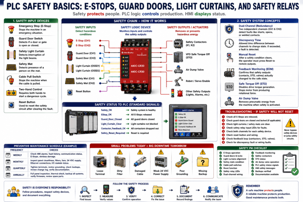
PLC Safety Basics
In industrial automation, safety is not just another PLC input.
Safety devices are used to protect people from hazardous machine motion, stored energy, electrical hazards, pneumatic movement, hydraulic force, robot motion, and other dangerous conditions.
Common safety devices include:
Emergency stop pushbuttons
Guard door switches
Safety interlock switches
Safety light curtains
Safety mats
Cable pull switches
Two-hand controls
Safety relays
Safety PLCs
Safety contactors
Air dump valves
Safe torque off circuits
A simple way to understand it is:
Standard PLC logic controls production.
Safety logic protects people.
That difference is critical.
Safety systems must be designed, installed, configured, tested, and maintained according to applicable codes, standards, risk assessment, and plant procedures. Rockwell’s Guardmaster safety relay manual emphasizes that installation, configuration, operation, and maintenance must be performed by suitably trained personnel and in accordance with applicable codes, laws, and standards.
Why Safety Is Different from Normal PLC Logic
A standard PLC input may tell the program:
A box is present.
A valve is open.
A motor is running.
A tank is full.
A safety input may tell the system:
An E-stop was pressed.
A guard door is open.
A light curtain was interrupted.
A safety mat is occupied.
A robot cell gate is open.
The consequences are different.
If a normal photoeye fails, the machine may miscount product.
If a safety device fails, a person may be exposed to hazardous motion.
That is why safety circuits are treated differently from normal machine control.
Safety Is Not Just an HMI Alarm
An HMI alarm can tell the operator something happened.
But an alarm does not guarantee hazardous motion is removed.
Example:
HMI Alarm:
Guard Door Open
That is useful information, but the safety function must actually remove or prevent hazardous energy.
A proper safety system may stop:
Motor run power
Servo enable
VFD safe torque
Pneumatic valve supply
Robot motion enable
Hydraulic actuator movement
Output power to hazardous devices
The HMI can display the safety condition, but the safety system must perform the protective function.
Basic Safety Chain
A simple machine safety chain has three major parts:
Safety Input Device
        ↓
Safety Logic Device
        ↓
Safety Output / Actuator
Example:
E-stop button
        ↓
Safety relay
        ↓
Safety contactors remove motor power
Another example:
Light curtain
        ↓
Safety PLC
        ↓
Safe torque off disables drive
The Guardmaster safety relay manual describes safety monitoring functions such as emergency stop, enabling switch, feedback monitoring, gate switch, safety light curtain, reset/restart, safety mat, SensaGuard, two-hand control, and output loop functions.
1. Emergency Stop
An emergency stop, or E-stop, is used to stop hazardous machine motion when there is an emergency.
Important idea:
E-stop is for emergency stopping.
It is not a normal cycle stop button.
A normal stop may stop the machine in a controlled production sequence.
An E-stop is intended for abnormal hazardous conditions.
Examples:
Person caught near moving equipment
Unexpected machine motion
Operator sees dangerous condition
Maintenance person needs immediate stop
Product jam creates unsafe condition
When pressed, the E-stop should place the machine into a safe condition according to the machine design and risk assessment.
E-Stop Troubleshooting Notes
When troubleshooting an E-stop circuit, check:
Is the E-stop physically pressed?
Is the button mechanically latched?
Does it reset mechanically?
Are both safety channels healthy?
Is the safety relay showing input fault?
Is reset required?
Is feedback monitoring satisfied?
Are contactors actually de-energized?
Is the PLC only monitoring status or controlling safety?
Important:
Never jumper an E-stop to “get production running.”Any safety bypass must follow plant procedure, authorization, risk assessment, and documentation.
2. Guard Door Interlocks
Guard doors prevent access to hazardous areas while the machine is operating.
A guard door switch may be used to detect:
Door closed
Door open
Door locked
Door unlocked
Actuator inserted
Safety channel healthy
Guard doors are common on:
Robot cells
Palletizers
Packaging machines
Conveyors
Presses
Indexing tables
Wrappers
Filling machines
When the door opens, the safety system may stop hazardous motion.
Guard Door vs Door Status on HMI
The safety switch may go to the safety relay or safety PLC.
The standard PLC may receive only a status signal.
Example:
Safety circuit:
Guard Door Switch → Safety Relay → Safety Outputs

Standard PLC status:
Safety Relay Aux Contact → PLC Input → HMI shows Guard Door Open
The PLC input is often for display and diagnostics.
It should not be assumed that a normal PLC input is performing the safety function.
3. Safety Light Curtains
A safety light curtain detects when a person or object enters a protected area.
Common applications:
Press loading area
Robot cell entry
Palletizer access point
Machine opening
Conveyor hazard zone
Packaging machine guard opening
When the light curtain beam is interrupted, the safety system must respond according to the safety design.
A safety light curtain is not the same as a normal photoeye.
Photoeye = product detection
Light curtain = personnel protection
That difference matters.
Light Curtain Troubleshooting Notes
Check:
Emitter powered
Receiver powered
Alignment
Blocked beams
Dirty lens
Safety relay input status
OSSD output status
Reset condition
Muting condition if used
Reflective surfaces
Cabling damage
If a light curtain is muted, verify the muting logic and sensors carefully.
Muting is safety-related and should not be treated like a normal bypass.
4. Safety Relay
A safety relay monitors safety input devices and controls safety outputs.
It may monitor:
E-stop channels
Guard door channels
Light curtain outputs
Safety mat
Two-hand control
Reset button
Feedback loop
Contactor monitoring
A standard relay may energize a coil and close contacts.
A safety relay is designed for safety monitoring and fault detection.
The Guardmaster manual includes topics such as pulse testing, input filtering, channel and discrepancy tests, safety monitoring functions, safety output functions, and troubleshooting. This shows that a safety relay is not just a “regular relay”; it performs monitored safety logic and diagnostics.
5. Safety PLC
A safety PLC is a controller designed for safety-related control functions.
It may handle:
Multiple E-stops
Multiple guard zones
Robot safety
Servo safe torque off
Light curtains
Safety mats
Muting
Zone control
Safety diagnostics
A safety PLC is different from a standard PLC.
Industrial automation material explains that safety controllers may take the form of a safety PLC or configurable safety controller, consolidating guard doors, E-stops, robot and servo safety inputs into one control point while still meeting safety requirements.
6. Dual-Channel Safety
Many safety devices use two channels.
Example:
Channel A
Channel B
Why?
Because two channels help detect faults such as:
Broken wire
Short to 24 VDC
Short to 0 VDC
Stuck contact
Welded contact
Cross fault between channels
Timing mismatch
A safety relay may compare both channels.
If one channel changes and the other does not, the relay may detect a discrepancy fault.
The Guardmaster manual includes channel and discrepancy tests, and it identifies recoverable fault examples such as cross loop faults, shorts to 24V or COM, input discrepancy, and reset/restart timing faults.
7. Discrepancy Time
Discrepancy time is the allowed time difference between safety channels changing state.
Example:
Channel A opens.
Channel B should also open within the allowed time.
If they do not match within the allowed time, the safety relay may fault.
Possible causes:
Bad E-stop contact
Bad guard switch channel
Loose wire
Wrong wiring
Mechanical issue
Faulty actuator
Channel short
Incorrect configuration
Discrepancy faults are valuable because they help detect unsafe wiring or device problems.
8. Manual Reset vs Automatic Reset
Safety systems may use manual reset or automatic reset depending on the application and risk assessment.
Manual Reset
The machine does not restart safety outputs until a reset button is pressed after the safety condition is restored.
Example:
E-stop released
Guard door closed
Light curtain clear
Operator presses Reset
Safety relay outputs turn ON
Manual reset helps prevent unexpected restart.
Automatic Reset
Safety outputs return automatically when the safety condition becomes healthy.
This may be acceptable for some lower-risk applications, but it must be evaluated carefully.
Important:
Reset does not mean start.
Reset only restores safety readiness.
The PLC/start logic should still control machine start.
A machine should not unexpectedly start simply because a guard door was closed or an E-stop was released.
9. Feedback Monitoring / EDM
Feedback monitoring is used to confirm that safety output devices actually changed state.
This is sometimes called:
EDM
External Device Monitoring
Feedback Monitoring
Contactor Monitoring
Example:
Safety relay output turns OFF.
Safety contactors should drop out.
Auxiliary feedback contacts prove they dropped out.
If a contactor welds, feedback monitoring can detect that the safety output device did not return to the expected state.
This is important because the safety relay output may be OFF, but a welded contactor could still leave hazardous power connected.
10. Safety Contactors
Safety contactors are commonly used to remove power from motors or other hazardous equipment.
They may be used as redundant contactors:
K1 Safety Contactor
K2 Safety Contactor
Why two?
Redundancy improves fault detection and safety reliability.
If one contactor welds, the other can still interrupt power, and the feedback loop can detect the problem.
A technician should check:
Contactor coil voltage
Auxiliary feedback contacts
Mechanical movement
Welded contacts
Safety relay output
Overload/contact path
Correct reset behavior
11. Safe Torque Off
Many modern VFDs and servo drives use Safe Torque Off, or STO.
STO disables the drive’s ability to produce torque.
Simple concept:
STO active = drive cannot generate motor torque.This can be used as part of a safety function when designed correctly.
Important:
STO is not the same as removing incoming power.
STO does not remove stored electrical energy inside the drive.
STO does not replace lockout/tagout.
For maintenance work, always follow LOTO and plant electrical safety procedures.
12. Air Dump Valves
Many machines use pneumatic motion.
A safety system may control an air dump valve.
When the safety circuit drops, the air dump valve may remove pneumatic energy from the machine.
Possible effects:
Cylinders retract
Cylinders stop moving
Air pressure vents
Machine loses pneumatic force
Actuators move to fail-safe position
Important:
Dumping air can cause movement.
Restoring air can also cause movement.
Always understand the machine’s pneumatic behavior.
Safety Circuit vs PLC Interlock
This is a very important distinction.
Safety Circuit
Protects people by removing or preventing hazardous motion.
Example:
Guard door open → safety relay drops outputs → motor power disabledPLC Interlock
Prevents machine operation based on process or machine conditions.
Example:
Low air pressure → PLC blocks auto cycleBoth are important, but they are not the same.
A PLC interlock should not be used as a substitute for a properly designed safety function.
Safety Status to PLC
The standard PLC often receives safety status signals.
Examples:
DI_Safety_Relay_OK
DI_Estop_OK
DI_Guard_Door_Closed
DI_Light_Curtain_Clear
DI_Safety_Reset_Required
DI_Safety_Contactor_Feedback_OK
These signals are useful for:
HMI diagnostics
Machine permissives
Alarm messages
Startup conditions
Maintenance troubleshooting
Example PLC logic:
Safety_OK
AND Auto_Mode
AND Start_Request
AND No_Faults
THEN Machine_Enable
But remember:
The PLC status bit reports safety condition.
It should not replace the safety circuit.
HMI Safety Diagnostics
A good HMI should help operators and technicians understand why the machine is not ready.
Useful HMI safety messages:
E-stop pressed
Guard door open
Light curtain blocked
Safety relay requires reset
Safety contactor feedback fault
Air dump valve not enabled
Robot safety not ready
Safety zone 2 not healthy
Bad HMI message:
Safety FaultBetter HMI message:
Safety Fault — Guard Door 2 Open. Close door and press Safety Reset.Even better:
Safety Fault — Guard Door 2 Channel Discrepancy. Check both safety channels and actuator alignment.Safety Reset Troubleshooting
If the machine safety circuit will not reset, check:
All E-stops released
All guard doors closed
Light curtain clear
Safety mat clear
Cable pull reset
Reset button working
Safety relay inputs healthy
Both safety channels match
Feedback loop satisfied
Contactors dropped out correctly
No discrepancy fault
No wiring short
Correct reset mode
No safety device damaged
Do not repeatedly press reset without understanding why it will not reset.
The reset failure is information.
Practical Example: E-Stop Pressed
Symptom
Machine will not start.
HMI shows:
E-stop ActiveTroubleshooting Path
1. Walk the machine and check all E-stop buttons.
2. Verify which E-stop zone is active if HMI shows zone detail.
3. Release the pressed E-stop.
4. Check safety relay input LEDs.
5. Check if safety reset is required.
6. Press reset if safe and authorized.
7. Verify safety relay output LEDs.
8. Verify PLC Safety_OK input.
9. Test machine start normally.
Do not bypass the E-stop circuit.
Find the actual device and restore it properly.
Practical Example: Guard Door Fault
Symptom
Machine stops when guard door closes, but safety relay will not reset.
Possible Causes
Door switch actuator misaligned
One safety channel not changing
Broken wire on one channel
Door switch damaged
Wrong replacement switch
Discrepancy fault
Feedback loop issue
Door lock not engaged
Troubleshooting Path
1. Check door physically closed.
2. Check switch actuator alignment.
3. Check safety relay channel LEDs.
4. Check both channels.
5. Check discrepancy fault.
6. Check wiring and connector.
7. Check reset requirement.
8. Check contactor feedback loop.
Practical Example: Light Curtain Blocked
Symptom
Safety circuit will not reset.
HMI shows:
Light Curtain BlockedPossible Causes
Product blocking beam
Person or object in protected area
Emitter/receiver misaligned
Dirty lens
Damaged cable
OSSD output fault
Muting sensors not correct
Reflective interference
Troubleshooting Path
1. Clear the protected area.
2. Clean emitter and receiver lens.
3. Check alignment LEDs.
4. Verify OSSD status.
5. Check safety relay input LEDs.
6. Check muting status if applicable.
7. Reset safety only after area is safe.
Practical Example: Safety Contactor Feedback Fault
Symptom
Safety reset fails.
HMI shows:
Safety Contactor Feedback FaultPossible Causes
Contactor welded
Auxiliary feedback contact stuck
Feedback wire broken
Contactor not dropping out
Wrong auxiliary contact used
Safety relay feedback loop open
Mechanical contactor issue
Troubleshooting Path
1. Verify safety contactors are de-energized.
2. Check mechanical state of contactors.
3. Check auxiliary feedback contacts.
4. Check feedback loop wiring.
5. Check safety relay feedback input.
6. Replace defective contactor if confirmed.
7. Verify reset and stop function after repair.
This is a serious fault. Do not simply bypass feedback monitoring.
Common Safety Troubleshooting Mistakes
1. Treating Safety Like Normal I/O
A safety input is not just another sensor.
It is part of a protective function.
2. Jumping Safety Contacts
Jumping safety circuits is dangerous and may violate plant safety procedures.
3. Ignoring Dual Channels
Both channels must be checked.
One channel can look good while the other has a problem.
4. Resetting Without Understanding
If safety will not reset, there is a reason.
Find the reason.
5. Assuming PLC Safety_OK Means Everything Is Safe
A standard PLC status bit is only a report.
The actual safety function must be verified in the safety system.
6. Not Checking Feedback Monitoring
If the safety relay requires contactor feedback, the safety outputs may not reset until the feedback loop is correct.
Safety Troubleshooting Checklist
1. Identify the safety zone.
2. Check HMI safety message.
3. Check all E-stops in that zone.
4. Check guard doors and locks.
5. Check light curtains and safety mats.
6. Check safety relay input LEDs.
7. Check both safety channels.
8. Check discrepancy or fault status.
9. Check reset button and reset mode.
10. Check safety output LEDs.
11. Check safety contactors.
12. Check feedback monitoring loop.
13. Verify PLC Safety_OK input.
14. Test normal start conditions.
15. Document the root cause.
Safety PM Checklist
During preventive maintenance, check:
E-stop physical operation
Guard door alignment
Safety switch mounting
Light curtain alignment and lens condition
Safety mat condition
Cable pull switch tension and reset
Safety relay status LEDs
Safety reset operation
Contactor feedback loop
Safety contactor condition
Air dump valve operation
STO wiring/status
HMI safety diagnostics
Safety circuit documentation
Testing safety devices must follow plant procedure and authorization.
Automation Technician Notes
For an Automation Technician, safety troubleshooting requires discipline.
The mindset should be:
Protect people first.
Do not bypass safety casually.
Understand the safety chain.
Check both channels.
Verify reset and feedback.
Document what was found.
When a safety circuit fails, the machine may be stopped, but the safety system may be doing exactly what it was designed to do.
Your job is not to “make it run” at any cost.
Your job is to restore safe operation correctly.
Key Terms
| Term | Meaning |
|---|---|
| E-Stop | Emergency stop device |
| Safety Relay | Device that monitors safety inputs and controls safety outputs |
| Safety PLC | Controller designed for safety-related functions |
| Guard Door Switch | Safety device monitoring access doors |
| Light Curtain | Optical safety device that detects entry into hazardous area |
| Dual Channel | Two safety signal paths used for fault detection |
| Discrepancy Time | Allowed time difference between safety channels |
| Manual Reset | Operator reset required after safety condition clears |
| EDM | External Device Monitoring |
| Safety Contactor | Contactor used in safety output circuit |
| STO | Safe Torque Off |
| Air Dump Valve | Valve used to remove pneumatic energy |
| Safety_OK | PLC status bit showing safety system is healthy |
| Safety Zone | Area or section protected by a safety circuit |
Final Thoughts
PLC safety is one of the most important topics for an Automation Technician.
A standard PLC controls the machine, but safety systems protect people.
The key idea is:
Safety input → Safety logic → Safety output → Hazardous energy removedA safety relay or safety PLC may monitor E-stops, guard doors, light curtains, reset buttons, and contactor feedback. The standard PLC may receive safety status for HMI display and machine permissives, but that status signal is not the same as the safety function itself.
The professional mindset is simple:
Do not bypass.
Do not guess.
Follow the safety chain.
Verify both channels.
Respect reset and feedback.
Restore safe operation.
A machine that runs is good.
A machine that runs safely is the goal.