31. PLC Preventive Maintenance: Keeping Control Systems Reliable ( 31 of 35 )
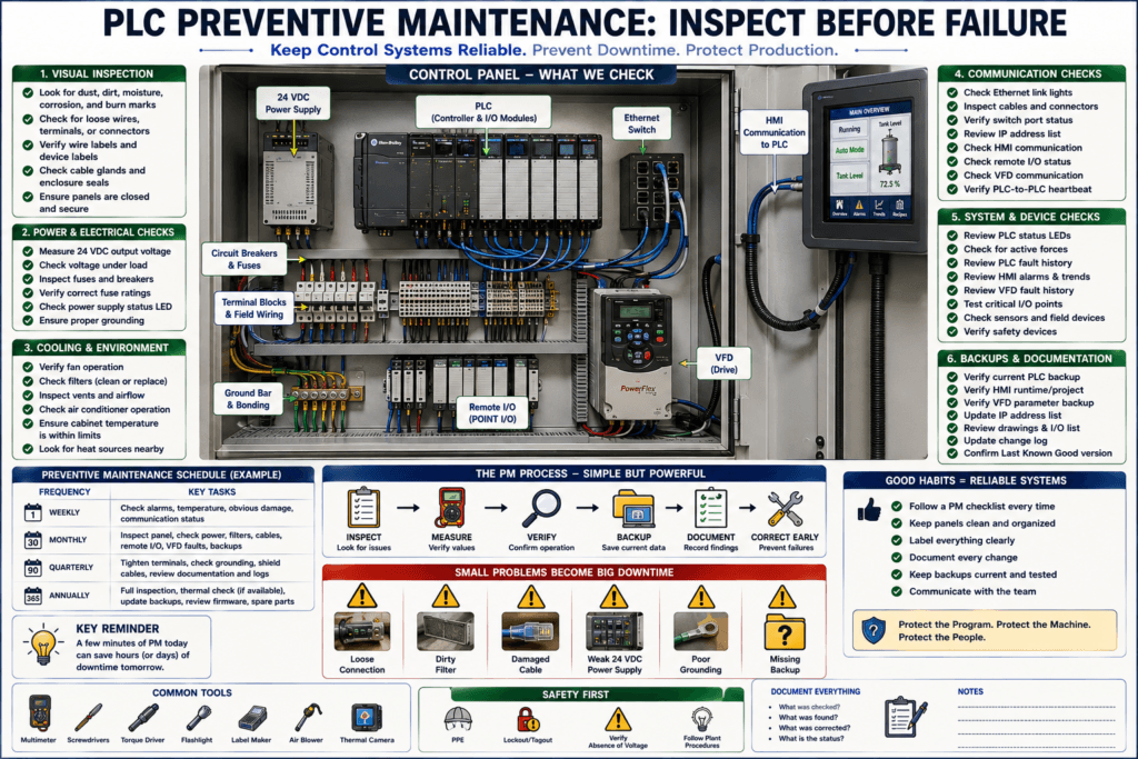
A PLC system can run for years with very few problems, but that does not mean it should be ignored.
A PLC panel needs preventive maintenance just like motors, gearboxes, sensors, VFDs, and pneumatic systems.
Many automation failures start small:
Loose terminal
Dirty panel filter
Weak 24 VDC power supply
Overheating cabinet
Dust buildup
Corrosion
Bad Ethernet cable
Unlabeled wire
Missing backup
Failing fan
Loose ground
If these issues are caught early, downtime can be reduced.
A simple way to understand preventive maintenance is:
Troubleshooting fixes problems after they happen.
Preventive maintenance finds problems before they stop the machine.
Why PLC Preventive Maintenance Matters
PLC systems are the control brain of the machine.
If the PLC system fails, the machine may stop completely.
PLC preventive maintenance helps improve:
Machine reliability
Troubleshooting speed
Electrical safety
Communication stability
Signal quality
Panel cleanliness
Backup readiness
Long-term equipment life
Downtime reduction
A good Automation Technician does not only repair faults.
A good technician also helps prevent them.
1. Inspect the Control Panel
Start with a visual inspection.
Look for:
Dust
Moisture
Corrosion
Loose wires
Burn marks
Hot spots
Damaged cable insulation
Missing wire labels
Open knockouts
Loose gland fittings
Poor wire duct covers
Unsealed panel doors
A quick visual inspection can reveal many hidden problems.
For example:
A small water mark inside a panel may explain random input faults.
A burnt terminal may explain voltage drops.
A loose Ethernet cable may explain HMI communication faults.
Do not underestimate visual inspection.
2. Check Panel Temperature
Heat damages electronics over time.
PLC CPUs, I/O modules, power supplies, Ethernet switches, VFDs, safety relays, and HMIs all have temperature limits.
Check:
Panel temperature
Fan operation
Air conditioner operation
Filter condition
Vent blockage
Heat marks
Device spacing
Sun exposure
VFD heat
Power supply heat
Common heat-related symptoms:
PLC faults after running for hours
HMI freezes
Power supply shuts down
VFD faults under load
Communication modules drop offline
Analog values become unstable
If the panel is too hot, fixing the heat problem may prevent repeat failures.
3. Check Cooling Fans and Filters
Many control panels use fans, filters, air conditioners, or heat exchangers.
Preventive checks:
Fan spinning correctly
Fan not noisy
Filter not clogged
Airflow not blocked
Cabinet vents clean
Air conditioner cooling correctly
Drain line clear
Door gasket sealed
A clogged filter can slowly overheat the panel.
The machine may run fine during cool weather and fail during hot days or heavy production.
4. Check the 24 VDC Power Supply
The 24 VDC power supply is one of the most important devices in a PLC panel.
It may power:
PLC modules
Sensors
Remote I/O
Relays
Solenoids
Ethernet switch
HMI
Safety relay
Encoders
Analog transmitters
Check:
Output voltage
Voltage under load
Power supply status LED
Loose terminals
Overload indication
Heat
Fan if equipped
Correct grounding
Fuse protection
A weak 24 VDC supply can cause strange problems:
Inputs flicker
Sensors drop out
Relays chatter
HMI reboots
Remote I/O faults
PLC resets
Solenoids fail to energize
Technician tip:
Do not only measure 24 VDC at the power supply.
Measure at the device that is failing.
Voltage can be good at the supply and bad at the field device because of wiring, terminals, fuses, or voltage drop.
5. Check Fuses and Circuit Protection
Fuses and breakers protect the control system.
During preventive maintenance, check:
Blown fuse indicators
Loose fuse holders
Correct fuse rating
Heat damage
Spare fuse availability
Breaker status
Terminal tightness
Circuit labels
A poor fuse holder can create intermittent voltage loss.
A wrong fuse rating can create safety or equipment protection issues.
Good documentation should show:
Fuse number
Circuit protected
Voltage
Current rating
Drawing reference
6. Tighten and Inspect Terminals
Loose terminals are one of the most common causes of intermittent faults.
Check terminals for:
Loose screws
Loose spring terminals
Wire pulled out slightly
Broken wire strands
Ferrule not seated
Multiple wires under one terminal
Insulation trapped under clamp
Corrosion
Heat discoloration
Important:
Follow plant electrical safety procedures before touching or tightening terminals.
Verify absence of voltage when required.
Intermittent faults often come from vibration and loose connections.
7. Inspect Grounding and Bonding
Grounding affects safety and signal reliability.
Check:
Panel ground connection
Ground bar tightness
PLC chassis ground
Power supply ground
VFD ground
Motor ground
Door bonding straps
DIN rail bonding if required
Shield drain connections
Loose ground wires
Paint under ground lugs
Poor grounding can contribute to:
Electrical noise
Analog signal instability
Communication faults
VFD interference
Encoder miscounts
Random input flickering
Grounding should be clean, tight, and intentional.
8. Inspect Shielded Cables
Shielded cables are used for sensitive signals.
Examples:
Analog 4–20 mA
0–10 VDC
Load cells
Encoders
Thermocouples
RTDs
Ethernet
Communication cables
VFD control signals
Check:
Shield drain connected correctly
Shield not touching wrong terminals
Cable jacket not damaged
Shield continuity
No long exposed shield pigtails
Cable not routed with VFD motor leads
Bad shield termination can create noise problems that look like bad sensors or bad PLC modules.
9. Check Ethernet and Communication Cables
Modern PLC systems depend heavily on Ethernet.
Inspect:
PLC Ethernet cable
HMI cable
Remote I/O cable
VFD network cable
Switch uplink
Patch panel
RJ45 connectors
Cable labels
Fiber connections if used
Switch port LEDs
Look for:
Broken locking tabs
Loose RJ45 connector
Damaged cable jacket
Cable pulled too tight
Unlabeled ports
Cable routed near high voltage
Switch port errors
A bad Ethernet cable can cause:
HMI communication fault
Remote I/O dropout
VFD communication fault
SCADA stale tags
Laptop cannot go online
PLC-to-PLC heartbeat loss
10. Check PLC and I/O Module Status LEDs
PLC modules usually provide diagnostic LEDs.
Check:
CPU Run LED
CPU Fault LED
Communication LED
I/O module status
Input channel LEDs
Output channel LEDs
Network adapter status
Remote I/O status
Force indicator
Battery indicator if applicable
Status LEDs are fast diagnostic tools.
Example:
Remote I/O adapter flashing red = communication or module issue.
Output LED ON but device OFF = check field power and output circuit.
Input LED OFF but sensor ON = check signal, common, and input terminal.
Document abnormal LED status before power cycling, because power cycling may temporarily hide the problem.
11. Check for Active Forces
Forces can create dangerous confusion.
During preventive maintenance, check:
Are any input forces installed?
Are any output forces installed?
Are forces enabled?
Is the controller force LED active?
Was a force left from troubleshooting?
A force should never be left active without strict control and documentation.
A forgotten force can cause:
False input status
Output operating unexpectedly
Incorrect troubleshooting
Hidden machine fault
Unsafe assumptions
Preventive maintenance should include verifying that no unauthorized forces are present.
12. Review PLC Fault Logs and Diagnostics
Many controllers, drives, and HMIs store diagnostic information.
Check:
Controller fault history
Major fault information
Minor faults
Module faults
Communication faults
VFD fault history
HMI alarm history
Remote I/O diagnostics
Safety relay diagnostics
Fault history can reveal problems before they become major failures.
Example:
Remote I/O had three brief communication losses this week.
Machine has not fully stopped yet, but the issue is developing.
That is exactly the type of problem preventive maintenance should catch.
13. Verify PLC Backups
Preventive maintenance should include backup verification.
Check:
Current PLC backup exists
Backup matches running machine
HMI runtime/project saved
VFD parameters saved
IP address list updated
Electrical drawings available
Change log updated
Last known good version identified
A backup is only useful if it is current and easy to find.
Bad situation:
PLC fails.
Multiple old backups exist.
Nobody knows which one is correct.
Good situation:
PLC fails.
Current running backup is clearly labeled.
Replacement recovery is controlled.
14. Review Program Changes
Ask:
Was the PLC program changed recently?
Was the HMI runtime changed?
Was a VFD replaced?
Was a remote I/O module replaced?
Was a sensor bypassed?
Was a module inhibited?
Was a network setting changed?
Recent changes should be documented.
If a machine has intermittent issues after a change, program compare and change logs become very useful.
15. Check HMI Screens and Alarms
The HMI should be checked during preventive maintenance.
Verify:
HMI communicates with PLC
Alarm banner works
Alarm history is accessible
Start/Stop buttons work correctly
Reset button works correctly
Manual screen works correctly
Trends update
Setpoints display correct values
Recipe screen loads correctly
Security levels work
Date/time is correct
Bad HMI alarms can slow troubleshooting.
Example:
Fault 17Better:
Conveyor 1 Motor Failed To Start — Check overload, starter feedback, and VFD ready status.16. Check VFDs and Drives
VFDs should be part of PLC preventive maintenance because they are often connected to the PLC system.
Check:
Drive fault history
Drive cooling fan
Heat sink dust
Parameter backup
Motor nameplate settings
Control source
Speed reference source
Network status
Ethernet adapter status
Grounding
Motor cable condition
Line/load wiring
Common warning signs:
Drive fan noisy
Drive runs hot
Repeated overcurrent faults
Communication faults
Loose control wiring
Wrong speed feedback
Motor current higher than normal
A VFD failure can appear as a PLC problem because the PLC may be waiting for drive feedback.
17. Check Remote I/O
Remote I/O should be inspected physically and online.
Check:
Adapter status LEDs
Module status LEDs
Ethernet link LEDs
24 VDC supply
Field power
Module seating
Terminal tightness
Cable condition
Network configuration
I/O tree health
Remote I/O faults can stop a machine even if the main PLC rack is healthy.
18. Check Sensors and Field Devices
Preventive maintenance is not only inside the panel.
Also inspect field devices:
Photoeyes
Proximity sensors
Limit switches
Pressure switches
Level switches
Valve feedback sensors
Motor feedback contacts
Encoders
Load cells
Analog transmitters
Look for:
Loose mounting
Misalignment
Dirty lens
Damaged cable
Loose connector
Water intrusion
Corrosion
Mechanical wear
Wrong sensing distance
Vibration damage
A sensor may work today but fail tomorrow because it is loose, dirty, or damaged.
19. Check Air and Pneumatic Devices Related to PLC Outputs
Many PLC outputs control pneumatic valves.
Check:
Air pressure
FRL condition
Solenoid valve operation
Manual override
Cylinder speed
Flow controls
Valve feedback
Air leaks
Tubing condition
Cylinder sensors
A PLC may command a solenoid correctly, but if air pressure is low or a cylinder is mechanically binding, the sequence may still fault.
20. Check Documentation Inside the Panel
A good panel should have useful documentation nearby.
Check for:
Electrical drawings
Panel layout
I/O list
IP address list
Fuse list
Device list
VFD parameter sheet
Safety circuit reference
PLC backup location
HMI backup location
If documentation is missing or outdated, troubleshooting will take longer during a breakdown.
Preventive Maintenance Schedule Example
Weekly Checks
Check HMI alarms and fault history
Check panel temperature
Check PLC/HMI communication status
Check VFD active faults
Check obvious cable or sensor damage
Monthly Checks
Inspect panel cleanliness
Check filters and fans
Check power supply voltage
Check Ethernet link status
Check remote I/O status
Review repeated alarms
Verify backup location
Quarterly Checks
Inspect terminals and wiring condition
Review grounding and shield terminations
Check VFD parameter backups
Review IP address list
Review drawings and change logs
Check PLC/HMI backup currency
Annual Checks
Full panel inspection
Thermal inspection if available
Backup all PLC/HMI/VFD/servo/robot systems
Review spare parts
Verify firmware/version documentation
Review network map
Review safety circuit documentation
The schedule depends on the machine criticality, environment, and plant procedures.
Practical Example: Preventing an HMI Communication Fault
Observation
During PM, the technician notices:
HMI Ethernet cable has a broken RJ45 locking tab.
Cable is loose at the switch port.
Possible Future Failure
HMI may randomly lose PLC communication during vibration.Preventive Action
Replace cable.
Label both ends.
Verify link lights.
Update network documentation if needed.
Monitor HMI communication.
This prevents downtime before operators report a fault.
Practical Example: Preventing Analog Signal Problems
Observation
A 4–20 mA analog cable is routed in the same duct as VFD motor leads.
Possible Future Failure
Tank level signal may jump when VFD runs.Preventive Action
Reroute analog cable away from VFD wiring.
Verify shield termination.
Check raw analog value stability.
Document correction.
This prevents false alarms and unstable process control.
Practical Example: Preventing Output Failure
Observation
A solenoid output terminal shows heat discoloration.
Possible Future Failure
Loose terminal may create voltage drop or intermittent solenoid operation.Preventive Action
Follow safety procedure.
Inspect terminal.
Repair or replace damaged terminal.
Verify voltage under load.
Test solenoid operation.
Document finding.
Common Preventive Maintenance Mistakes
1. Only Cleaning the Panel
Cleaning is good, but PM is more than cleaning.
You also need to check power, wiring, grounding, communication, backups, and diagnostics.
2. Not Checking Backups
A machine can look healthy today, but if the PLC fails tomorrow and there is no backup, downtime can be long.
3. Ignoring Repeated Minor Alarms
Repeated small alarms may indicate a developing problem.
Example:
Occasional remote I/O communication fault
Occasional low air pressure alarm
Occasional motor feedback timeout
These should be investigated.
4. Not Documenting Findings
A PM that is not documented loses value.
Record what was checked, what was found, and what was corrected.
5. Not Following Safety Procedures
Preventive maintenance still involves electrical hazards, moving equipment, stored energy, and control circuits.
Follow plant safety rules.
PLC Preventive Maintenance Checklist
Panel clean and dry
No signs of water or corrosion
Panel temperature acceptable
Fans and filters working
24 VDC power supply checked
Fuses and breakers inspected
Terminals inspected
Grounding and bonding checked
Shielded cables inspected
Ethernet cables inspected
PLC status LEDs normal
I/O module LEDs normal
Remote I/O healthy
No unauthorized forces active
PLC fault history reviewed
HMI alarms reviewed
VFD fault history reviewed
PLC/HMI/VFD backups verified
IP address list updated
Drawings available and current
Sensors and field devices inspected
Findings documented
Automation Technician Notes
For an Automation Technician, preventive maintenance is about asking:
What can fail soon?
What has failed before?
What looks abnormal?
What is loose, hot, dirty, damaged, unlabeled, outdated, or undocumented?
The best PM finds weak points before production finds them.
A small correction during PM can prevent a major downtime event later.
Key Terms
| Term | Meaning |
|---|---|
| Preventive Maintenance | Planned inspection to prevent failures |
| Control Panel | Enclosure containing PLC and control devices |
| 24 VDC Power Supply | Main control voltage source for PLC devices |
| Terminal Block | Connection point for field wiring |
| Grounding | Electrical bonding for safety and noise control |
| Shielded Cable | Cable used to protect sensitive signals |
| Remote I/O | I/O modules located away from main PLC |
| HMI Alarm History | Record of machine alarms |
| VFD Fault History | Stored drive faults and warnings |
| Backup Verification | Confirming current files are saved and usable |
| Change Log | Record of program or configuration changes |
| PM Checklist | Standard list of inspection points |
Final Thoughts
PLC preventive maintenance helps keep automation systems reliable.
It is not only about wiping dust from a panel.
It is about checking the complete control system:
Power
Grounding
Wiring
Cooling
Communication
I/O modules
Field devices
HMI alarms
VFD diagnostics
Backups
Documentation
A strong Automation Technician understands that many breakdowns can be prevented by catching small problems early.
The professional mindset is:
Inspect before failure.
Document what you find.
Correct small issues early.
Keep backups ready.
Protect production uptime.
Preventive maintenance does not replace troubleshooting.
It reduces how often emergency troubleshooting is needed.