28. HMI Basics for PLC Technicians ( 28 of 35 )
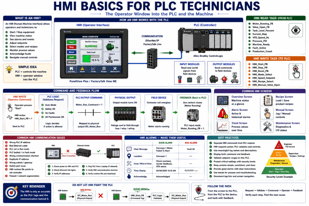
An HMI, or Human Machine Interface, is the screen that allows operators and technicians to interact with a machine or process.
A PLC controls the machine, but the HMI gives the operator a way to:
Start and stop equipment
View machine status
See alarms
Adjust setpoints
Select modes
Monitor process values
View trends
Acknowledge faults
Navigate manual controls
A simple way to understand it:
PLC = controls the machine
HMI = operator window into the PLC
The PLC source material explains that a PLC by itself generally does not provide a practical way for operators to view signal values, monitor variables, or adjust parameters. An HMI solves that problem by giving selective read/write access to specific PLC memory locations through a dedicated screen or industrial computer.
What Is an HMI?
An HMI is an operator interface used to display and control machine information.
Common HMI devices include:
Panel-mounted touchscreens
Industrial PCs
SCADA workstations
Operator interface terminals
Text displays
Graphic terminals
In Allen-Bradley systems, common examples include:
PanelView Plus
FactoryTalk View ME
FactoryTalk View SE
PanelView 800
Industrial PCs running HMI software
The HMI communicates with the PLC, reads PLC tags, writes operator commands, and displays machine information in a format that is easier to understand than raw PLC logic.
HMI vs PLC
The HMI and PLC are connected, but they do different jobs.
| Device | Main Job |
|---|---|
| PLC | Executes control logic |
| HMI | Displays information and allows operator interaction |
| PLC Input | Real field signal into the controller |
| HMI Button | Screen object that writes a command tag |
| PLC Output | Physical command to a device |
| HMI Indicator | Visual display of a PLC tag |
Example:
Operator presses Start on HMI
        ↓
HMI writes Start_Command tag
        ↓
PLC reads Start_Command
        ↓
PLC checks permissives and interlocks
        ↓
PLC commands motor output
The HMI does not replace the PLC logic. It gives the operator a controlled way to interact with that logic.
What an HMI Commonly Displays
A good HMI should show useful machine information.
Common HMI display items include:
Machine status
Auto / Manual mode
Running / Stopped indication
Fault and alarm messages
Motor status
Valve status
VFD status
Tank levels
Temperature
Pressure
Flow
Speed
Production count
Recipe number
Current step
Setpoints
Manual controls
Maintenance screens
A well-designed HMI helps the operator understand what the machine is doing and what condition is stopping it.
HMI Read Tags and Write Tags
This is one of the most important concepts.
An HMI can read PLC tags and write to PLC tags.
Read Tag
A read tag is information the HMI displays.
Examples:
Motor_Running_FB
Tank_Level_Percent
Machine_Faulted
Current_Step
VFD_Fault_Code
Valve_Open_FB
The HMI reads these values from the PLC and displays them.
Write Tag
A write tag is a command or setpoint the HMI sends to the PLC.
Examples:
HMI_Start_PB
HMI_Stop_PB
HMI_Reset_PB
HMI_Mode_Select
HMI_Speed_Setpoint
HMI_Recipe_Select
HMI_Manual_Valve_Open
The HMI writes these values into PLC memory.
Then the PLC logic decides what to do with them.
Very Important: Do Not Let HMI Fight the PLC
A common mistake is allowing the HMI and PLC logic to write to the same tag.
Example of a bad design:
HMI button writes directly to Motor_Run_Command
PLC ladder logic also writes to Motor_Run_Command
This can create unpredictable behavior because two different sources are trying to control the same memory bit.
The source material gives this same warning: PLC input data should usually be read-only to the HMI, and you should avoid allowing both HMI objects and PLC logic to write to the same memory location because this creates data conflicts similar to duplicate coils in ladder logic.
Better design:
HMI_Start_PB → PLC logic → Motor_Run_Command → Physical OutputThe HMI requests an action.
The PLC decides if the action is allowed.
HMI Buttons
HMI buttons are used to send operator commands to the PLC.
Common buttons:
Start
Stop
Reset
Acknowledge Alarm
Manual Open
Manual Close
Jog Forward
Jog Reverse
Auto Mode
Manual Mode
Recipe Load
A good PLC program should not trust the HMI button alone.
Example:
HMI_Start_PB
AND Auto_Mode
AND Safety_OK
AND Permissives_OK
AND NOT Faulted
THEN Motor_Run_Command
The HMI gives the request, but the PLC validates the conditions.
Momentary vs Maintained Buttons
HMI buttons can behave differently.
Momentary Button
A momentary HMI button is ON only while pressed.
Example:
Operator presses Start
HMI_Start_PB turns ON
Operator releases Start
HMI_Start_PB turns OFF
Best for:
Start requests
Reset requests
Jog commands
Acknowledge buttons
Maintained Button
A maintained HMI button stays ON or OFF after being pressed.
Example:
Press once = ON
Press again = OFF
Best for:
Enable selections
Manual mode selection
Feature enable
Bypass selection with authorization
Be careful with maintained buttons because they can remain active after the operator leaves the screen.
HMI Indicators
HMI indicators display machine status.
Examples:
Motor Running = green
Motor Faulted = red
Valve Open = green
Valve Closed = gray
Air Pressure Low = yellow
Machine Ready = blue/green
Fault Active = red
Indicators should be connected to meaningful PLC tags.
Good examples:
DI_Motor_Running_FB
Valve_Open_Status
Machine_Ready
Fault_Active
VFD_Running
Avoid showing only command bits.
Example:
Motor_Run_Command = PLC wants motor to run
Motor_Running_FB = motor is actually running
For HMI status, feedback is usually more valuable than command.
HMI Setpoints
An HMI setpoint allows the operator to change a numeric value.
Common setpoints:
Speed setpoint
Temperature setpoint
Pressure setpoint
Fill level
Batch quantity
Timer preset
Counter preset
Recipe value
Alarm limit
Example:
Operator enters 45.0 Hz
        ↓
HMI writes HMI_Speed_Setpoint
        ↓
PLC validates range
        ↓
PLC moves value to VFD_Speed_Command
Good PLC logic should validate setpoints.
Example:
If HMI_Speed_Setpoint >= Min_Speed
AND HMI_Speed_Setpoint <= Max_Speed
Then accept value
Never allow an HMI setpoint to write unsafe or unrealistic values without validation.
HMI Alarms
HMI alarms tell the operator what is wrong.
Common alarms:
Motor Failed To Start
Valve Failed To Open
Low Air Pressure
E-Stop Active
Guard Door Open
VFD Faulted
Communication Fault
Tank High Level
Tank Low Level
Encoder Fault
Product Jam
A good alarm should answer:
What happened?
Where did it happen?
What should the operator or technician check?
Bad alarm:
Fault 34Better alarm:
Conveyor 1 Motor Failed To Start — Check overload, starter feedback, and VFD status.HMI Alarm States
Common alarm states include:
Active
Acknowledged
Cleared
Historical
Shelved / suppressed, depending on system
Important:
Acknowledge does not fix the fault.
Reset does not fix the root cause.
An acknowledge usually means the operator has seen the alarm.
A reset usually clears a latched PLC fault if the fault condition is no longer active.
HMI Trends
Trends show values over time.
Useful trend values:
Tank level
Pressure
Temperature
Flow
VFD speed
Motor current
Weight
pH
Conductivity
Production rate
Trends help answer:
Did the value slowly drift?
Did it spike suddenly?
Did it change when a VFD started?
Did the pressure drop before the fault?
Did the temperature overshoot?
The source material notes that modern HMIs can support graphic trending, data archival, advanced alarming, and even web server access, allowing the HMI to store historical data while the PLC focuses on real-time control.
HMI Recipes
Recipes allow operators to load groups of setpoints for different products.
Example:
Recipe 1 — Small Bottle
Speed = 35 Hz
Fill Time = 2.5 sec
Target Count = 12
Recipe 2 — Large Bottle
Speed = 28 Hz
Fill Time = 4.0 sec
Target Count = 6
When the operator selects a recipe, the HMI or PLC loads values into active setpoint tags.
Good recipe design should include:
Recipe name
Recipe number
Validated ranges
Operator confirmation
Download/load status
Change history if available
Security level
HMI Security
Not every operator should have access to every screen or setting.
Common HMI security levels:
Operator
Maintenance
Supervisor
Engineer
Administrator
Examples:
| Function | Suggested Access |
|---|---|
| Start / Stop | Operator |
| Alarm acknowledge | Operator |
| Manual controls | Maintenance |
| Change recipe | Supervisor / Maintenance |
| Change critical setpoints | Maintenance / Engineer |
| Bypass devices | Restricted |
| User management | Administrator |
Security is important because a wrong HMI value can cause equipment problems or unsafe machine behavior.
HMI Communication with PLC
An HMI must communicate with the PLC to read and write tags.
Common communication methods:
Ethernet/IP
Modbus TCP
Serial communication
OPC
FactoryTalk Linx / RSLinx
SCADA drivers
For Allen-Bradley systems, a common path is:
HMI → Ethernet Switch → PLCThe source material describes HMIs as connecting to PLCs through digital network cables such as Ethernet and acting as a window into PLC memory for operators.
Common HMI Communication Problems
Common issues include:
Wrong PLC IP address
Bad Ethernet cable
Bad switch port
HMI shortcut/path incorrect
PLC powered off
PLC faulted
Duplicate IP
Wrong subnet
Wrong communication driver
Runtime file points to old controller
Firewall or network segmentation issue
Remote I/O/network issue
Typical HMI alarms:
PLC Communication Error
Cannot connect to controller
Shortcut failed
Device unavailable
Tag not found
Connection timeout
HMI Troubleshooting Path
When an HMI is not communicating with a PLC, check:
1. Is the PLC powered and running?
2. Is the HMI powered?
3. Are Ethernet link lights ON?
4. Is the Ethernet switch powered?
5. Is the PLC IP correct?
6. Is the HMI IP correct?
7. Are both devices on the correct subnet?
8. Is the HMI communication shortcut/path correct?
9. Can a laptop ping the PLC?
10. Was the PLC replaced recently?
11. Was the HMI runtime file changed?
12. Was the network switch or cable changed?
This is very important for real plant troubleshooting.
HMI Screens a Technician Should Understand
A good machine HMI usually has several screens.
Overview Screen
Shows machine status and main process values.
Machine running/stopped
Current step
Fault status
Main motors/valves
Production count
Manual Screen
Allows controlled manual operation.
Jog conveyor
Open/close valve
Extend/retract cylinder
Turn on pump
Alarm Screen
Shows active and historical alarms.
Alarm message
Time active
Acknowledged status
Reset status
Trend Screen
Shows process values over time.
Pressure
Temperature
Level
Speed
Flow
Recipe Screen
Allows product configuration.
Recipe number
Setpoints
Load button
Save button
Validation
Maintenance Screen
Shows diagnostics for technicians.
I/O status
Device feedback
VFD fault code
PLC communication status
Cycle timers
Current step logic
A strong technician learns where to find each of these screens quickly.
HMI Design Best Practices
A good HMI should be clear, not confusing.
Best practices:
Use clear machine status
Use consistent colors
Show faults clearly
Show current step
Show command and feedback separately
Use meaningful alarm text
Do not overload screen with unnecessary animation
Use proper units
Use correct decimal places
Validate setpoint ranges
Protect critical screens with security
Provide maintenance diagnostic screens
Command vs Feedback on HMI
This is a major troubleshooting point.
The HMI should make it clear whether a device is only commanded or actually running.
Example:
Motor Command = ON
Motor Feedback = OFF
This means:
PLC wants motor to run,
but motor has not proven running.
That could indicate:
Starter not pulling in
VFD not running
Overload tripped
Feedback wire issue
Aux contact failed
A good HMI helps the technician see that difference.
HMI Tags: Good Naming Matters
Good tag names make the HMI easier to build and troubleshoot.
Good examples:
HMI_Start_PB
HMI_Stop_PB
HMI_Reset_PB
HMI_Auto_Mode_Select
HMI_Speed_Setpoint
Machine_Status_Text
Current_Step_Number
Fault_Active
Alarm_Acknowledge
Motor_Running_FB
Valve_Open_FB
Tank_Level_Percent
The source material explains that consistent tag naming helps group related tags together, making them easier to locate in the tag database, especially because many tag editors list names alphabetically.
Common HMI Mistakes
1. HMI Writes Directly to Outputs
Bad:
HMI button writes directly to DO_Motor_RunBetter:
HMI_Start_PB → PLC logic → Motor_Run_Command → DO_Motor_Run2. No Feedback Display
Bad:
Show only Motor CommandBetter:
Show Motor Command and Motor Running Feedback3. Poor Alarm Text
Bad:
Fault 17Better:
Reject Conveyor Failed To Start — Check overload, VFD ready, and motor feedback.4. No Security on Critical Settings
Critical setpoints, bypasses, and manual controls should not be open to everyone.
5. HMI Reads Wrong PLC Tag
The HMI may show a value, but it may be reading the wrong tag.
Always compare:
PLC tag online
HMI object connection
HMI displayed value
Practical Example: HMI Start Button Does Nothing
Symptom
Operator presses Start on the HMI, but the conveyor does not run.
Troubleshooting Path
1. Does the HMI button change the HMI_Start_PB tag?
2. Does the PLC see HMI_Start_PB?
3. Is the PLC in Auto Mode?
4. Are permissives OK?
5. Are interlocks OK?
6. Is any fault latched?
7. Does Conveyor_Run_Command turn ON?
8. Does DO_Conveyor_Run turn ON?
9. Does motor feedback turn ON?
Possible causes:
HMI button linked to wrong tag
PLC not seeing HMI command
Machine not in correct mode
Fault active
Output issue
Motor feedback issue
Communication problem
Practical Example: HMI Shows Wrong Tank Level
Symptom
HMI shows tank level at 0%, but tank has product.
Troubleshooting Path
1. Check local transmitter display.
2. Measure 4–20 mA signal.
3. Check PLC raw analog value.
4. Check PLC scaled value.
5. Check HMI tag connection.
6. Check HMI decimal/scaling display.
7. Check if HMI is reading raw tag instead of scaled tag.
Possible causes:
Transmitter issue
Analog wiring issue
PLC scaling issue
HMI reading wrong tag
HMI display format wrong
Communication issue
Practical Example: HMI Communication Fault
Symptom
HMI displays:
Check PLC CommunicationTroubleshooting Path
1. Check if PLC is powered.
2. Check if PLC is in Run Mode.
3. Check PLC fault LED.
4. Check Ethernet cable.
5. Check switch port LEDs.
6. Check HMI IP address.
7. Check PLC IP address.
8. Check HMI communication shortcut.
9. Check if PLC was replaced.
10. Check if runtime file points to the correct controller.
This is one of the most common real-world HMI troubleshooting problems.
Automation Technician Notes
For an Automation Technician, the HMI is not only an operator screen.
It is also a troubleshooting tool.
A good technician uses the HMI to check:
Current machine state
Active fault
Missing permissive
Current step
Device command
Device feedback
Setpoints
Actual values
VFD status
Trend history
Alarm history
But remember:
The HMI is only as accurate as the PLC tags and communication behind it.If the HMI looks wrong, verify the PLC tag online.
HMI Troubleshooting Checklist
1. Is the HMI powered?
2. Is the HMI communicating with the PLC?
3. Is the PLC powered and running?
4. Are IP addresses correct?
5. Is the HMI reading the correct PLC tag?
6. Is the HMI writing to the correct command tag?
7. Is the PLC logic using that command tag?
8. Are commands separated from outputs?
9. Are inputs read-only to the HMI?
10. Are alarms connected to correct PLC fault bits?
11. Are trends reading scaled engineering values?
12. Are setpoint limits configured?
13. Is security working correctly?
14. Was the HMI runtime recently changed?
15. Was the PLC replaced or downloaded?
Key Terms
| Term | Meaning |
|---|---|
| HMI | Human Machine Interface |
| OIT | Operator Interface Terminal |
| PLC Tag | Data point inside the PLC |
| Read Tag | HMI displays this PLC value |
| Write Tag | HMI sends this command/value to PLC |
| Setpoint | Operator-adjustable target value |
| Alarm | Message showing abnormal condition |
| Trend | Historical graph of a value |
| Recipe | Group of saved machine settings |
| Runtime File | HMI file running on the terminal |
| Communication Shortcut | HMI path to the PLC |
| Feedback | Signal proving device operation |
| Command | Request for device operation |
| Security Level | Access control for users/screens |
Final Thoughts
An HMI is the operator’s window into the PLC.
It allows operators to start and stop equipment, view machine status, adjust setpoints, acknowledge alarms, select recipes, and monitor trends.
For an Automation Technician, the HMI is also an important troubleshooting tool.
But the most important rule is:
The HMI requests and displays.
The PLC decides and controls.
A good HMI design separates commands from outputs, displays feedback clearly, protects critical settings, provides meaningful alarms, and helps technicians find the root cause faster.
When troubleshooting HMI problems, always verify:
HMI object → PLC tag → PLC logic → field device → feedbackThat path will tell you where the problem really is.