18. Program Control Instructions: JSR, MCR, JMP, and Fault Routine
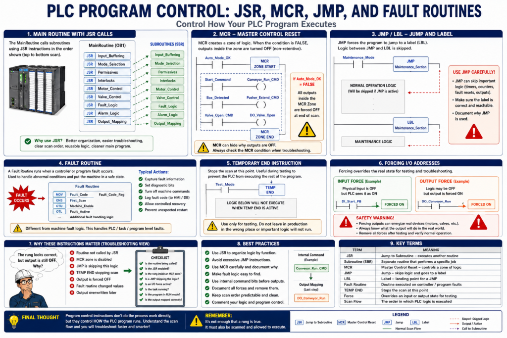
In PLC programming, not every instruction directly turns on a motor, counts a box, or starts a timer.
Some instructions are used to control how the PLC program executes.
These are called program control instructions.
They help organize the program, call subroutines, control sections of logic, jump over logic when needed, handle special conditions, and respond to processor or program faults.
Common program control concepts include:
JSR — Jump to Subroutine
SBR — Subroutine
RET — Return
MCR — Master Control Reset
JMP — Jump
LBL — Label
Fault Routine
Temporary End
Forcing
According to Programmable Logic Controllers, 6th Edition, program control instructions include master control reset, jump and label instructions, subroutine functions, immediate input/output instructions, forcing, safety circuitry, fault routines, and temporary end instructions.
Why Program Control Instructions Matter
A PLC program can become very large.
A real industrial machine may include logic for:
Inputs
Outputs
Motor control
Valve control
Modes
Permissives
Interlocks
Faults
Alarms
Counters
Timers
HMI commands
Manual controls
Auto sequence
Network communication
VFD control
Safety feedback
If all of this logic is placed in one long routine with no structure, troubleshooting becomes difficult.
Program control instructions help organize logic into sections.
For example:
Main Routine
    ↓
Input Buffering
    ↓
Mode Selection
    ↓
Permissives
    ↓
Motor Logic
    ↓
Valve Logic
    ↓
Fault Logic
    ↓
Output Mapping
This makes the program easier to read, monitor, and troubleshoot.
1. JSR — Jump to Subroutine
A JSR instruction means Jump to Subroutine.
It tells the PLC to go execute another routine.
In simple terms:
JSR = Go run this routineExample:
MainRoutine calls Motor_Control routine
MainRoutine calls Valve_Control routine
MainRoutine calls Fault_Logic routine
A JSR is very useful because it allows the program to be divided into organized sections.
JSR Example
A clean MainRoutine may look like this:
JSR Input_Buffering
JSR Mode_Selection
JSR Permissives
JSR Interlocks
JSR Motor_Control
JSR Valve_Control
JSR Fault_Logic
JSR Alarm_Logic
JSR Output_Mapping
This structure is easier to troubleshoot than having hundreds of rungs mixed together in one place.
Why JSR Is Useful
JSR instructions help with:
Program organization
Troubleshooting
Separating machine functions
Making logic easier to read
Reducing confusion
Building reusable structures
Keeping scan order clear
For an Automation Technician, JSR instructions are important because they tell you where the logic is being executed.
A routine may exist in the project, but if there is no JSR calling it, the PLC may not be scanning that routine.
Important Technician Note About JSR
A common troubleshooting mistake is opening a routine and assuming it is running.
But in PLC programming:
A routine must be called or scheduled to execute.
If the routine is not being called, the logic inside may not be active.
Example:
Motor_Control routine exists
But MainRoutine does not call it with JSR
Result: Motor_Control logic is not executed
So always check:
Is the routine being called?
Is the JSR enabled?
Is the task executing?
Is the program in the correct mode?
2. Subroutines
A subroutine is a separate section of logic that performs a specific job.
Examples:
Input_Buffering
Conveyor_Control
Pump_Control
Valve_Control
Alarm_Logic
Fault_Reset
HMI_Status
Output_Mapping
Each subroutine should have a clear purpose.
A good subroutine name tells the technician what type of logic is inside.
Good Subroutine Structure
Example for a small machine:
MainRoutine
    JSR Input_Buffering
    JSR HMI_Commands
    JSR Mode_Logic
    JSR Conveyor_Control
    JSR Valve_Control
    JSR Fault_Logic
    JSR Alarm_Logic
    JSR Output_Mapping
This is a professional structure because the scan order is predictable.
3. MCR — Master Control Reset
MCR stands for Master Control Reset.
An MCR instruction creates a controlled zone of logic.
When the MCR zone is enabled, the logic inside works normally.
When the MCR zone is disabled, the non-retentive outputs inside the zone are forced off by the PLC scan.
Simple idea:
MCR enabled  = logic inside can operate
MCR disabled = outputs inside are de-energized
MCR Example Concept
Imagine a section of logic that should only work when the machine is in Auto Mode.
Auto_Mode_Enable
        ↓
MCR Zone
        ↓
Auto conveyor logic
Auto valve logic
Auto sequence logic
When Auto Mode is OFF, the auto logic zone is disabled.
MCR Warning
MCR can be powerful, but it can also be confusing.
If a technician does not notice the MCR zone, they may think a rung should be turning ON an output, but the MCR is preventing the output from energizing.
Possible symptom:
The rung looks true
But the output stays OFF
Possible cause:
MCR zone is disabledMCR Best Practice
Use MCR carefully.
Do not use MCR as a replacement for good permissive and interlock logic.
Better modern practice is often:
Motor_Command = Start_Request
                AND Auto_Mode
                AND Permissives_OK
                AND Interlocks_OK
                AND NOT Faulted
This style is usually easier to troubleshoot because the reason for the output being OFF is visible in the rung.
4. JMP and LBL — Jump and Label Instructions
The JMP instruction tells the PLC to jump to a specific LBL, or label.
Simple idea:
JMP = Jump over logic
LBL = Landing point
The PLC skips the logic between the jump instruction and the label.
JMP / LBL Example Concept
If Maintenance_Mode = ON
JMP to Maintenance_Section

Normal operation logic
Normal sequence logic

LBL Maintenance_Section
Maintenance logic
This can be useful in some cases, but it can also make programs harder to troubleshoot.
Why JMP Can Be Dangerous
JMP instructions can hide logic from the normal scan.
If the PLC jumps over certain rungs, those rungs may not execute.
This can create confusing behavior.
Example:
Counter reset rung is skipped
Fault logic is skipped
Output command rung is skipped
Timer is not scanned
This may cause unexpected results.
Technician Warning About JMP
When troubleshooting a program, always check whether the logic is being skipped.
Ask:
Is there a JMP instruction before this rung?
Is the PLC jumping over this logic?
Is the LBL located after the skipped section?
Is a timer or counter not being scanned because of a jump?
Timers and counters can behave unexpectedly if they are not scanned consistently.
5. Fault Routine
A fault routine is a routine used to respond to certain PLC faults or program faults.
Its purpose is to give the controller a programmed way to handle abnormal conditions.
A fault routine may be used to:
Capture fault information
Set diagnostic bits
Log fault codes
Place machine logic in a safe state
Allow controlled recovery
Prevent unexpected restart
Fault Routine vs Machine Fault Logic
Do not confuse a PLC fault routine with normal machine fault logic.
Machine Fault Logic
This is normal logic inside the user program.
Examples:
Motor failed to start
Valve failed to open
VFD fault active
Overload tripped
Box jam detected
Low air pressure
Door not closed
PLC Fault Routine
This handles controller/program-level faults.
Examples:
Math overflow
Major fault
Program execution issue
Module-related fault handling
Processor fault response
Both are important, but they are not the same thing.
6. Temporary End Instruction
A temporary end instruction is used during testing or troubleshooting to stop the scan at a certain point in the program.
This may be useful when commissioning or isolating a section of logic.
However, it must be used carefully.
If left in the wrong place, it can prevent important logic from executing.
Possible result:
Outputs do not update correctly
Fault logic is skipped
Alarms are not processed
Subroutines after the temporary end do not execute
For real plant equipment, this should be controlled and documented.
7. Forcing I/O Addresses
Forcing is not exactly a normal program control instruction, but it affects how the PLC behaves.
A force allows a technician or programmer to force an input or output to a certain state.
Examples:
Force input ON
Force input OFF
Force output ON
Force output OFF
Forcing can be useful for testing, but it can be dangerous.
Input Force vs Output Force
Input Force
An input force changes what the PLC logic sees.
Example:
Physical input is OFF
Input force makes PLC logic see it as ON
This may be used to simulate a sensor during testing.
Output Force
An output force commands a physical output regardless of normal logic conditions.
Example:
Logic says output should be OFF
Output force turns output ON
This can energize real devices.
That means it can move equipment, start motors, open valves, or create unsafe motion.
Forcing Safety Note
Before forcing anything, always ask:
What device will turn ON?
Can anything move?
Can anyone be injured?
Is air, hydraulic, or electrical energy present?
Is the area clear?
Do I have authorization?
Is this documented?
Can I remove the force after testing?
Never use forcing casually.
Why Program Control Instructions Can Make Troubleshooting Hard
Program control instructions can make logic more powerful, but they can also make troubleshooting more difficult if used poorly.
Problems may happen when:
A routine exists but is not called
A JSR is disabled
A JMP skips important logic
An MCR zone disables outputs
A temporary end stops the scan early
An I/O force overrides real-world conditions
A fault routine changes values unexpectedly
This is why a technician must understand not only the rung, but also whether the rung is actually being scanned and allowed to execute.
Practical Example: Routine Not Being Scanned
Problem
A conveyor output never turns ON.
The rung inside Conveyor_Control looks correct.
What the technician notices
Start command is ON
Stop is OK
Overload is OK
Rung looks logically correct
But output never energizes
Possible cause
Conveyor_Control routine is not being called by JSRTroubleshooting step
Go to MainRoutine and verify:
JSR Conveyor_ControlIf the JSR is missing or disabled, the routine logic may not execute.
Practical Example: MCR Blocking an Output
Problem
A solenoid output does not energize even though the rung looks true.
Possible cause
The rung is inside an MCR zone.
MCR zone is disabled
Output stays OFF
Troubleshooting step
Check the condition enabling the MCR zone.
Example:
Auto_Mode_Enable
Safety_OK
Machine_Enable
If the MCR is false, the zone may be disabling the output logic.
Practical Example: JMP Skipping Fault Reset
Problem
A fault reset button does not clear the fault.
Possible cause
A JMP instruction is skipping the rung where the reset logic is located.
Troubleshooting step
Check scan flow:
Is the reset rung being scanned?
Is a JMP active before the reset rung?
Where is the matching LBL?
This is one reason why excessive JMP use can make troubleshooting difficult.
Good Program Organization for Technicians
A clean program should make the scan order easy to follow.
Recommended structure:
1. Input Mapping
2. Signal Conditioning / Debounce
3. HMI Commands
4. Mode Selection
5. Permissives
6. Interlocks
7. Fault Detection
8. Alarm Handling
9. Machine Commands
10. Output Mapping
This structure helps technicians understand:
What the PLC sees
What the PLC allows
What the PLC blocks
What the PLC commands
What the PLC outputs
Best Practices for Program Control Instructions
1. Use JSR for Organization
Use subroutines to separate logic by function.
Good examples:
JSR Input_Buffering
JSR Conveyor_Control
JSR Valve_Control
JSR Fault_Logic
JSR Output_Mapping
2. Avoid Excessive JMP Instructions
JMP can make the program harder to follow.
Use it only when there is a clear reason.
3. Be Careful with MCR Zones
MCR zones can hide why outputs are OFF.
Use clear comments and labels.
4. Keep Fault Logic Visible
Machine fault logic should be easy to find.
Good examples:
Motor_Failed_To_Start
Valve_Failed_To_Open
VFD_Faulted
Air_Pressure_Low
5. Document Forces
Forces should be temporary and documented.
Before leaving the machine:
Remove forces
Verify machine operation
Notify team
Document what was tested
6. Separate Commands from Physical Outputs
Instead of commanding physical outputs from many places, use internal command bits.
Example:
Conveyor_Run_Command → DO_Conveyor_Run
Valve_Open_Command → DO_Valve_Open
Horn_Command → DO_Alarm_Horn
This reduces confusion.
Troubleshooting Checklist
When logic is not behaving as expected, ask:
1. Is the PLC in Run Mode?
2. Is the correct task running?
3. Is the program scheduled?
4. Is the routine being called by JSR?
5. Is the rung being scanned?
6. Is an MCR zone disabling the logic?
7. Is a JMP skipping this logic?
8. Is a temporary end stopping the scan?
9. Is an input or output forced?
10. Is a fault routine changing values?
11. Is the output written somewhere else?
12. Is the physical output mapped correctly?
This checklist can save a lot of troubleshooting time.
Automation Technician Notes
For an Automation Technician, program control instructions are important because they answer one critical question:
Is this logic actually being executed?
Do not only look at whether a rung appears true.
Also verify:
Is the routine being scanned?
Is the JSR active?
Is the rung inside an MCR zone?
Is a JMP skipping the rung?
Is the output being overwritten later?
Is a force overriding the logic?
A rung that looks correct can still have no effect if the PLC scan flow does not reach it or if another instruction overrides it.
Key Terms
| Term | Meaning |
|---|---|
| Program Control | Instructions that affect how PLC logic executes |
| JSR | Jump to Subroutine |
| Subroutine | Separate routine used to organize logic |
| MCR | Master Control Reset zone |
| JMP | Jump instruction used to skip logic |
| LBL | Label where a JMP lands |
| Fault Routine | Routine used to handle certain PLC/controller faults |
| Temporary End | Instruction used to stop program scan at a point |
| Force | Manual override of an input or output state |
| Scan Flow | Order in which PLC logic is executed |
| Output Mapping | Final section where internal commands drive physical outputs |
Final Thoughts
Program control instructions are not always the first instructions a beginner learns, but they are very important in real industrial PLC programs.
Instructions like JSR, MCR, JMP, and fault routines affect how the PLC scans and executes logic.
For troubleshooting, the key is not only knowing whether a rung is true or false.
The real question is:
Is the PLC actually scanning this logic, and is anything overriding it?Once you understand program control instructions, large PLC programs become much easier to navigate and troubleshoot.