1. What Is Industrial Electricity and Why Automation Technicians Need It?
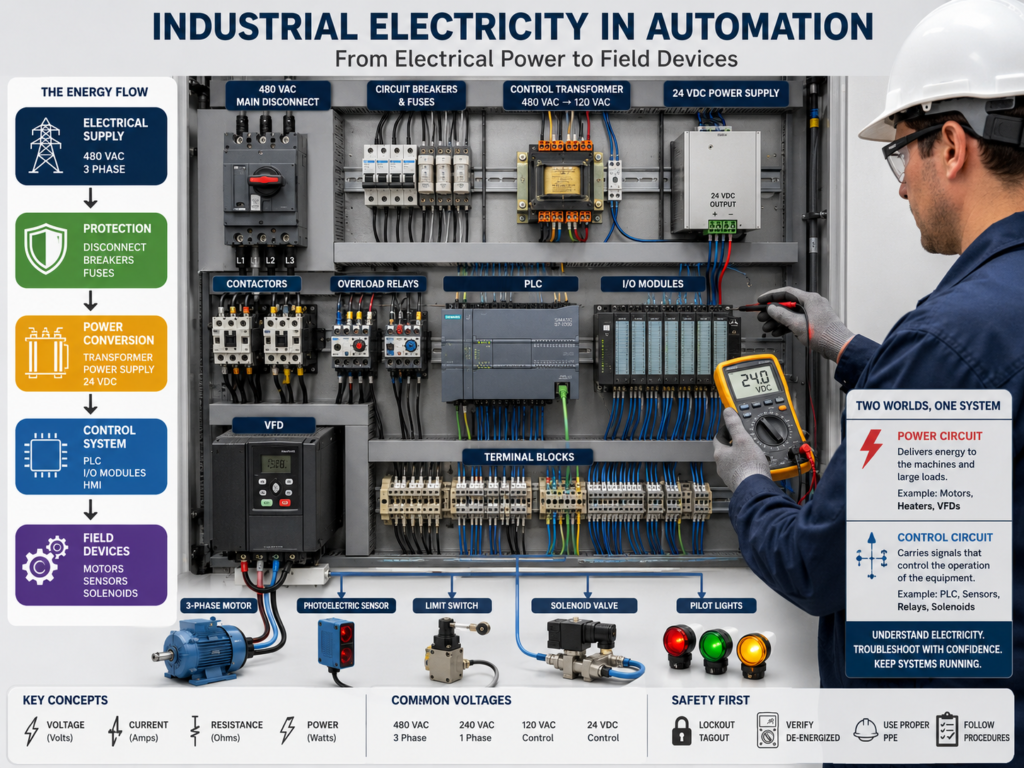
Industrial automation depends completely on electricity.
A PLC cannot read a sensor without electrical power. A VFD cannot control a motor without a three-phase supply. A solenoid valve cannot move without an energized coil. Even the most advanced automation system becomes useless when its electrical foundation fails.
For this reason, an automation technician must understand more than PLC programming. The technician must understand how electrical power enters a machine, how it is distributed, how it is controlled, and how it reaches the final device.
The CEKIT electricity course begins with the idea that electricity is a form of energy associated with the movement of electrons through a material. It also explains that a useful electrical circuit requires a voltage source, conductors, and a load connected through a complete path. These basic concepts remain essential when working with modern industrial control systems.
What Is Industrial Electricity?
Industrial electricity is the generation, distribution, control, and use of electrical energy inside industrial equipment and facilities.
In an automation system, electricity performs two main functions:
- It supplies power to operate equipment.
- It carries control signals between devices.
These two functions create two important areas inside most machines:
Power Circuit
and
Control Circuit
The power circuit delivers the energy required by large loads such as motors, heaters, pumps, compressors, and industrial drives.
The control circuit determines when and how those loads operate.
A Simple Industrial Automation Example
Consider a conveyor controlled by a PLC and a VFD.
The system may contain:
480 VAC Incoming Power
        ↓
Main Disconnect
        ↓
Circuit Protection
        ↓
VFD
        ↓
Three-Phase Motor
The control system may use:
120 VAC or 480 VAC
        ↓
Control Transformer or Power Supply
        ↓
24 VDC
        ↓
PLC, Sensors, Relays and Solenoids
The VFD supplies controlled electrical power to the motor.
The PLC decides when the conveyor should start or stop.
A photoelectric sensor detects a box.
A pushbutton allows an operator to start the system.
An overload, safety relay, or fault condition can prevent operation.
Although this system appears to be controlled by software, every command still depends on a physical electrical circuit.
The Two Electrical Worlds Inside a Control Panel
1. The Power Circuit
The power circuit carries the electrical energy required by the machine’s main loads.
Typical power-circuit components include:
- Main disconnect
- Circuit breaker
- Fuses
- Motor starter
- Contactor
- Overload relay
- VFD
- Motor
- Heater
- Transformer
A typical motor power circuit may look like this:
L1 ─────────────┐
L2 ─────────────┼─ Disconnect → Fuses → Contactor → Overload → Motor
L3 ─────────────┘
The power circuit commonly operates at voltages such as:
- 208 VAC
- 230 VAC
- 240 VAC
- 460 VAC
- 480 VAC
- 600 VAC
The exact voltage depends on the facility, machine, and electrical system.
2. The Control Circuit
The control circuit carries the signals that command the machine.
Typical control-circuit components include:
- Pushbuttons
- Selector switches
- Limit switches
- Proximity sensors
- Photoelectric sensors
- PLC inputs
- PLC outputs
- Control relays
- Contactor coils
- Solenoid valves
- Pilot lights
A basic control circuit could look like this:
24 VDC+
   ↓
Emergency Stop
   ↓
Stop Pushbutton
   ↓
Start Pushbutton
   ↓
PLC Input
The PLC evaluates the signal and may energize an output:
PLC Output
   ↓
Interposing Relay
   ↓
Contactor Coil
   ↓
Motor Starter
The control circuit does not necessarily deliver the energy used by the motor. Instead, it controls the component that connects the motor to the power circuit.
Electricity as Energy and Information
In industrial automation, electrical current can represent either energy or information.
Electricity as energy
Examples include:
- A motor converting electricity into mechanical movement.
- A heater converting electricity into heat.
- A lamp converting electricity into light.
- A solenoid converting electricity into mechanical motion.
Electricity as information
Examples include:
- A 24 VDC signal indicating that a sensor is active.
- A PLC output commanding a valve to open.
- A 4–20 mA signal representing tank level.
- A 0–10 V signal representing speed.
- An encoder pulse representing motor position.
- An Ethernet signal carrying PLC data.
This is a major difference between general electrical work and industrial automation.
The automation technician must understand both the energy path and the signal path.
The Basic Electrical Circuit
A useful electrical circuit normally contains four fundamental elements:
1. Source
The source provides electrical potential.
Examples:
- Utility power
- Transformer
- 24 VDC power supply
- Battery
- Generator
- VFD output
2. Conductors
Conductors create the path through which current flows.
Examples:
- Copper wires
- Control cables
- Motor leads
- Terminal blocks
- Printed circuit board traces
3. Load
The load converts electrical energy into another form of energy.
Examples:
- Motor
- Solenoid coil
- Relay coil
- Pilot light
- Heater
- PLC input circuit
4. Complete return path
Current must have a complete path from the source, through the load, and back to the source.
A simple circuit can be represented as:
Source Positive
      ↓
    Switch
      ↓
     Load
      ↓
Source Common
When the path is complete, current can flow.
When the path is interrupted, current stops.
Open, Closed, and Short Circuits
Understanding these three conditions is essential for troubleshooting.
Open circuit
An open circuit has an interrupted current path.
Examples:
- Open fuse
- Broken wire
- Open pushbutton
- Disconnected terminal
- Failed relay contact
- Burned coil winding
24 VDC+ ─── Switch Open ──X── Coil ─── 0 VDCThe coil does not energize because current cannot complete the circuit.
Closed circuit
A closed circuit has a complete path for current.
24 VDC+ ─── Switch Closed ─── Coil ─── 0 VDCThe coil energizes because current can flow through the complete path.
Short circuit
A short circuit creates an unintended low-resistance path.
24 VDC+ ──────────┐
                  ├── Direct unintended connection
0 VDC ────────────┘
A short circuit can produce excessive current, open a fuse, trip a breaker, damage wiring, or destroy an electronic output.
Common Industrial Voltage Levels
An automation technician may encounter several voltage levels inside the same machine.
| Voltage | Typical application |
|---|---|
| 480 VAC three-phase | Motors, VFDs, heaters and large loads |
| 240 VAC | Motors, heaters and auxiliary equipment |
| 120 VAC | Control transformers, receptacles and some control circuits |
| 24 VDC | PLCs, sensors, relays, solenoids and control devices |
| 10 VDC reference | Potentiometers and VFD speed references |
| 0–10 VDC | Analog control and instrumentation |
| 4–20 mA | Industrial instrumentation and process signals |
A single control panel may therefore contain high-voltage power wiring and low-voltage control wiring at the same time.
This is why proper labeling, wire separation, grounding, documentation, and safe measurement practices are critical.
Why Automation Technicians Must Understand Electricity
PLC troubleshooting requires electrical knowledge
Suppose the PLC program shows that an output instruction is ON, but the solenoid valve does not activate.
The problem could be:
- No power at the output module.
- Open output fuse.
- Failed PLC output channel.
- Broken field wire.
- Loose terminal.
- Wrong DC common connection.
- Open solenoid coil.
- Incorrect output-module type.
- Mechanical valve failure.
Programming knowledge alone cannot identify the cause.
The technician must measure the actual electrical circuit.
VFD troubleshooting requires electrical knowledge
A VFD fault may be caused by:
- Missing input phase.
- Low incoming voltage.
- Motor short circuit.
- Ground fault.
- Damaged motor cable.
- Excessive load.
- Incorrect grounding.
- Failed cooling fan.
- Loose power connection.
- Incorrect motor parameters.
The VFD fault code provides direction, but electrical measurements confirm the actual cause.
Sensor troubleshooting requires electrical knowledge
A sensor may appear healthy because its indicator light is ON, but the PLC input remains OFF.
Possible causes include:
- Incorrect PNP/NPN compatibility.
- Missing 24 VDC supply.
- Open signal conductor.
- Incorrect input common.
- Failed PLC input.
- Excessive voltage drop.
- Incorrect sensor wiring.
- Damaged connector.
Understanding voltage, current paths, and input circuits allows the technician to find the exact failure.
The Industrial Energy Path
A useful troubleshooting method is to divide the system into stages:
1. Electrical Supply
        ↓
2. Disconnect and Protection
        ↓
3. Voltage Conversion
        ↓
4. Control System
        ↓
5. Output Device
        ↓
6. Field Load
For example:
480 VAC Supply
        ↓
Main Disconnect
        ↓
Circuit Breaker
        ↓
Control Transformer
        ↓
24 VDC Power Supply
        ↓
PLC Output
        ↓
Relay
        ↓
Solenoid Valve
When a device fails, the technician can follow this path one stage at a time.
This is much more effective than replacing components based on assumptions.
Electricity and PLC Logic Are Connected
PLC logic represents conditions inside the controller, but those conditions normally originate from electrical devices.
Consider this ladder instruction:
|----[ XIC Start_PB ]----------------( Motor_Request )----|The tag Start_PB becomes true only when the PLC input module receives the proper electrical signal.
The real path may be:
24 VDC+
   ↓
Start Pushbutton
   ↓
Terminal Block
   ↓
PLC Input Channel
   ↓
Input Common
   ↓
24 VDC-
Therefore, ladder logic and electrical wiring cannot be treated as separate subjects.
A good automation technician follows both:
Electrical Signal
→ PLC Input
→ Program Logic
→ PLC Output
→ Field Device
Real Plant Example
An operator reports:
“The pump will not start.”
A technician should not immediately assume that the motor, VFD, or PLC is defective.
The troubleshooting process could be:
Step 1 — Verify incoming power
Check whether the disconnect, breaker, and VFD have the correct voltage.
Step 2 — Check the control system
Verify that the PLC and 24 VDC power supply are operating.
Step 3 — Check the start request
Determine whether the pushbutton or HMI command reaches the PLC.
Step 4 — Check permissives and interlocks
Verify conditions such as:
- Emergency stop healthy
- Overload healthy
- Tank level permissive
- Valve position
- Motor ready
- No active fault
Step 5 — Check the PLC output
Determine whether the program is commanding the pump.
Step 6 — Check the field circuit
Verify whether the output signal reaches the VFD, contactor, or relay.
Step 7 — Check the load
Verify the motor, cable, coupling, pump, and mechanical load.
This approach combines electrical knowledge, PLC logic, instrumentation, and mechanical inspection.
Electrical Safety Comes First
Before troubleshooting any industrial electrical system:
- Follow the facility’s electrical safety program.
- Apply lockout/tagout when required.
- Identify all energy sources.
- Verify the absence of voltage with an appropriately rated test instrument.
- Use the correct personal protective equipment.
- Never assume that a circuit is de-energized.
- Do not work beyond your authorization or training.
- Follow the machine drawings and manufacturer instructions.
The uploaded course also emphasizes that a circuit should never be assumed de-energized and that it must be verified using an appropriate test instrument. This remains one of the most important electrical safety principles.
The publication is older, so modern workplace work practices, PPE selection, voltage-rated tools, approach boundaries, arc-flash requirements, and lockout/tagout procedures must follow current facility policies and applicable standards.
Common Beginner Mistakes
Mistake 1 — Looking only at the PLC program
An instruction being true does not prove that voltage is reaching the field device.
Mistake 2 — Replacing parts without measuring
Parts should not be replaced until the circuit has been tested and the failure isolated.
Mistake 3 — Confusing neutral, ground, and DC common
These conductors can serve different purposes and should not automatically be treated as interchangeable.
Mistake 4 — Measuring resistance on an energized circuit
Resistance and continuity tests should be performed only after the circuit has been safely isolated and verified de-energized.
Mistake 5 — Assuming that an indicator light proves the device works
An LED can show that part of a device has power without proving that the complete control circuit is functioning.
Quick Reference
| Element | Purpose | Industrial example |
|---|---|---|
| Source | Provides voltage | Power supply or transformer |
| Conductor | Carries current | Copper control wire |
| Protection | Limits fault damage | Fuse or circuit breaker |
| Control device | Commands operation | PLC, relay or pushbutton |
| Load | Uses electrical energy | Motor, solenoid or heater |
| Return path | Completes the circuit | Neutral or DC common |
Key Takeaways
Industrial automation begins with electricity.
A technician must understand:
- How power enters a machine.
- How power is protected.
- How voltages are transformed.
- How sensors send signals.
- How PLC inputs receive those signals.
- How PLC outputs control loads.
- How motors, contactors, VFDs and solenoids operate.
- How to trace a circuit using measurements.
The most useful troubleshooting mindset is:
Follow the energy.
Follow the signal.
Verify every step.
Do not guess.
Practice Questions
Question 1
A PLC output indicator is ON, but the contactor does not energize.
Name three possible electrical causes.
Question 2
What is the difference between a power circuit and a control circuit?
Question 3
Why does an electrical load require a complete return path?
Question 4
Arrange these components in a logical energy path:
PLC Output
Main Disconnect
Solenoid Valve
24 VDC Power Supply
Circuit Breaker
Question 5
A photoelectric sensor has power, but the PLC input remains OFF.
What measurements would you perform before replacing the sensor?