1. What Is Industrial Instrumentation?
A Practical Guide for Automation Technicians
Industrial instrumentation is one of the most important areas in automation because it connects the real physical process to the control system.
A PLC, HMI, or SCADA system cannot directly “see” pressure, temperature, level, flow, weight, or pH. These are physical process variables. Instruments are the devices that measure those variables and convert them into signals the control system can understand.
In simple terms:
Industrial instrumentation is the field of measuring, monitoring, transmitting, controlling, and troubleshooting process variables in an industrial system.
This topic can become very deep, but for an automation technician, the goal is practical: understand how the instrument works, what signal it sends, how the PLC reads it, and how to troubleshoot it when the process value does not look correct.
The book Lessons In Industrial Instrumentation introduces industrial instrumentation by connecting real process examples such as boiler water level control, wastewater disinfection, chemical reactor temperature control, indicators, recorders, process switches, alarms, and instrumentation documentation. It also covers key technician areas such as P&IDs, loop diagrams, instrument connections, 4–20 mA signals, PLC analog I/O, HART, Modbus, calibration, and troubleshooting.
Why Instrumentation Matters in Automation
In an industrial plant, automation depends on accurate information from the field.
For example:
- A pump should not start if the tank level is too low.
- A heater should stop if the temperature gets too high.
- A valve may need to open based on pressure or flow.
- A conveyor may stop if a sensor detects a missing product.
- An HMI alarm may warn the operator when a process variable is outside the normal range.
All of these decisions depend on instruments.
Without reliable instrumentation, the PLC logic may be correct, but the machine or process can still behave incorrectly because the information coming from the field is wrong.
A good automation technician should always think this way:
Before blaming the PLC logic, verify the field instrument, wiring, signal, scaling, and process condition.
What Does an Instrument Measure?
Industrial instruments measure process variables.
A process variable is a physical condition in the process that needs to be monitored or controlled.
Common Process Variables
| Process Variable | Example in the Field |
|---|---|
| Pressure | Compressed air, steam, hydraulic pressure, water pressure |
| Temperature | Ovens, tanks, heat exchangers, process lines |
| Level | Tanks, hoppers, sumps, silos |
| Flow | Water, chemicals, air, product transfer |
| Weight | Scales, batching systems, filling machines |
| pH | Water treatment, chemical processes |
| Conductivity | Water quality, cleaning systems |
| Gas concentration | LEL, oxygen, toxic gas detection |
For an automation technician, these variables are important because they are often used in:
- PLC permissives
- Interlocks
- Alarms
- Fault logic
- HMI displays
- Trending
- Process control loops
- Startup checks
- Safety-related decisions
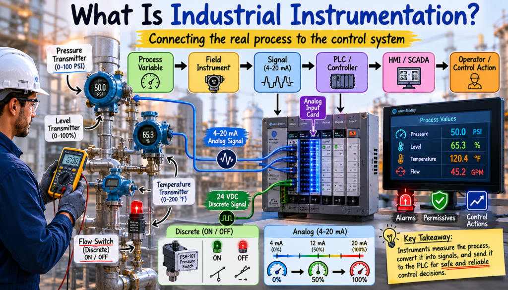
The Basic Instrumentation Path
Most instrumentation systems follow a simple path:
Process Variable → Field Instrument → Signal → PLC / Controller → HMI / SCADA → Operator or Control ActionExample:
Tank Level → Level Transmitter → 4–20 mA Signal → PLC Analog Input → HMI Level Display → Pump ControlThe technician needs to understand each part of that path.
If the HMI level value looks wrong, the problem could be in several places:
- The process level may actually be wrong.
- The transmitter may be out of calibration.
- The 4–20 mA signal may be incorrect.
- The wiring may be loose or damaged.
- The analog input card may have a problem.
- The PLC scaling may be incorrect.
- The HMI tag may be pointing to the wrong value.
This is why instrumentation troubleshooting requires a complete view of the system, not just one device.
Instruments vs Sensors vs Transmitters
These terms are often used together, but they are not always the same.
Sensor
A sensor detects a physical condition.
Examples:
- RTD sensing temperature
- Pressure sensing element
- Load cell sensing weight
- pH electrode sensing chemical activity
- Proximity sensor detecting metal
The sensor is the part that physically reacts to the process.
Transmitter
A transmitter converts the measurement into a standard signal that can be sent to a PLC, controller, or indicator.
Common transmitter output signals include:
- 4–20 mA
- 0–10 VDC
- HART
- Modbus
- Ethernet
- Foundation Fieldbus
Example:
A pressure transmitter may measure 0–100 PSI and output 4–20 mA.
0 PSI   = 4 mA
50 PSI  = 12 mA
100 PSI = 20 mA
Instrument
An instrument is a general term. It may refer to a sensor, transmitter, switch, indicator, recorder, controller, or analyzer.
Examples:
- Pressure transmitter
- Temperature switch
- Level indicator
- Flowmeter
- pH analyzer
- Control valve positioner
- I/P transducer
Discrete Instruments vs Analog Instruments
One of the first things an automation technician should understand is the difference between discrete and analog instrumentation.
Discrete Instrument
A discrete instrument gives an ON/OFF signal.
Examples:
- Pressure switch
- Level switch
- Flow switch
- Limit switch
- Temperature switch
- Proximity switch
Example:
Low Air Pressure Switch = ON or OFFThe PLC only sees a digital condition:
Input ON  = Pressure OK
Input OFF = Low Pressure or Fault Condition
Discrete instruments are commonly used for:
- Machine permissives
- Alarm conditions
- Interlocks
- Position feedback
- Start/stop decisions
- Safety-related monitoring
Analog Instrument
An analog instrument sends a variable signal that represents a changing process value.
Examples:
- Pressure transmitter
- Level transmitter
- Temperature transmitter
- Flow transmitter
- Weight transmitter
- pH transmitter
Example:
4–20 mA = 0–100 PSIThe PLC receives a changing analog value and scales it into engineering units.
Raw Analog Input → Scaling Logic → PSI, GPM, °F, %, Gallons, etc.Analog instruments are commonly used for:
- HMI displays
- Process control
- Trending
- PID loops
- Alarm setpoints
- Data logging
- Production monitoring
Common Instrumentation Signals
Industrial instruments communicate with control systems using standard signals.
Common Signal Types
| Signal | Common Use |
|---|---|
| 24 VDC discrete | Switches, sensors, feedback devices |
| 4–20 mA | Most common analog process signal |
| 0–10 VDC | Analog signal, often used in some controls |
| RTD signal | Temperature measurement |
| Thermocouple signal | Temperature measurement |
| HART | Smart transmitter communication over 4–20 mA |
| Modbus | Digital communication with meters, analyzers, drives |
| Ethernet/IP | PLC and industrial network communication |
| Pneumatic 3–15 PSI | Older or pneumatic control systems |
For automation technicians, 4–20 mA is one of the most important signals to master because it is widely used in pressure, level, flow, temperature, and analytical measurement.
The Role of the PLC
The PLC does not usually understand the process variable directly. It reads the electrical or digital signal from the instrument.
Example:
A pressure transmitter may send 4–20 mA to the PLC analog input card.
The PLC may first see this as a raw number.
Example:
Raw Input Count = 16384Then the PLC logic scales that raw value into engineering units.
Example:
Scaled Pressure = 50 PSIThen the HMI displays:
Tank Pressure: 50 PSIThis means the technician must understand both sides:
- The field side
Instrument, wiring, power supply, loop current, calibration. - The control side
PLC input card, raw value, scaling, tags, HMI display, alarms.
Instrumentation and Troubleshooting
Instrumentation troubleshooting is one of the most valuable skills for an automation technician.
When a process value looks wrong, do not jump immediately to replacing the instrument.
A professional troubleshooting approach is:
Verify the Process → Verify the Instrument → Verify the Signal → Verify the PLC Input → Verify the Scaling → Verify the HMIExample Problem
The HMI shows:
Tank Level = 0%But the operator says the tank is half full.
Possible causes:
- The level transmitter has no power.
- The 4–20 mA loop is open.
- The transmitter is out of calibration.
- The analog input card is not reading correctly.
- The PLC scaling is wrong.
- The HMI tag is incorrect.
- The instrument isolation valve is closed.
- The actual process condition is different from what the operator thinks.
A strong technician does not guess. A strong technician measures, verifies, and follows the signal path.
Instrumentation and Control Logic
Instrumentation is not only about measurement. It directly affects PLC logic.
For example, a pressure transmitter can be used for:
- Low pressure alarm
- High pressure alarm
- High-high pressure trip
- Pump start permissive
- Pump shutdown interlock
- HMI pressure display
- Trend recording
- PID control
Example PLC logic concept:
IF Tank_Level > Minimum_Start_Level
AND Pump_Not_Faulted
AND Valve_Open_Feedback = TRUE
THEN Allow_Pump_Start
In this example, the instrument is part of the permissive logic. If the level reading is wrong, the PLC decision may also be wrong.
This is why instrumentation must be trusted, tested, and maintained.
Instrumentation Documents Technicians Should Know
A good automation technician should be comfortable reading basic instrumentation documentation.
Important documents include:
| Document | Purpose |
|---|---|
| P&ID | Shows process equipment, piping, valves, instruments, and control relationships |
| Loop Diagram | Shows wiring and signal path for one instrument loop |
| Instrument Datasheet | Shows instrument range, signal type, process connection, power, and specifications |
| Calibration Sheet | Shows as-found and as-left calibration results |
| Wiring Diagram | Shows terminal connections and electrical wiring |
| I/O List | Shows PLC input/output addresses and instrument tags |
The most important one for troubleshooting is often the loop diagram because it shows how the field instrument connects to power, terminals, junction boxes, PLC input cards, and sometimes shields or test points.
Practical Example: Pressure Transmitter to PLC
Let’s say we have this instrument:
PT-101
Pressure Transmitter
Range: 0–100 PSI
Output: 4–20 mA
PLC Tag: Tank_Pressure_PSI
The signal relationship is:
| Pressure | Signal |
|---|---|
| 0 PSI | 4 mA |
| 25 PSI | 8 mA |
| 50 PSI | 12 mA |
| 75 PSI | 16 mA |
| 100 PSI | 20 mA |
The PLC may use this pressure value for:
- HMI display
- High pressure alarm
- Low pressure alarm
- Pump permissive
- Shutdown interlock
- Data trending
If the HMI shows 0 PSI, the technician should check:
- Is there actual pressure in the process?
- Is the transmitter powered?
- Is the loop current around 4 mA, 12 mA, or 20 mA?
- Is the PLC analog input receiving the signal?
- Is the scaling correct?
- Is the HMI displaying the correct tag?
What an Automation Technician Should Master
Industrial instrumentation is a large field, but an automation technician should focus on practical mastery.
Core Skills
An automation technician should know how to:
- Identify common instruments in the field.
- Read basic P&ID symbols.
- Understand instrument tags like PT, TT, LT, FT, PSH, LSL, and XV.
- Measure 4–20 mA loop current.
- Recognize bad signal conditions.
- Understand analog input scaling.
- Troubleshoot field wiring.
- Verify transmitter range.
- Understand zero and span.
- Support calibration checks.
- Compare field readings with PLC/HMI values.
- Understand alarms, permissives, and interlocks.
- Follow a loop diagram.
- Communicate findings clearly to maintenance, engineering, and operations.
Key Takeaway
Industrial instrumentation is the bridge between the physical process and the automation system.
The instrument measures what is happening in the real world. The signal carries that information to the PLC. The PLC uses that information to display values, trigger alarms, control equipment, and protect the process.
For an automation technician, instrumentation is not just theory. It is a daily troubleshooting skill.
When something does not look right on the HMI, the best technician follows the signal path:
Process → Instrument → Wiring → PLC Input → Scaling → HMI → Control LogicThat mindset is what separates random troubleshooting from professional industrial troubleshooting.
Final Thoughts
Industrial instrumentation can look complicated at first because it includes physics, electricity, process control, calibration, documentation, and communication protocols.
But the foundation is simple:
Measure the process, convert it into a usable signal, send it to the control system, and use that information to make safe and reliable control decisions.
As automation technicians, we do not need to learn everything at once. We build the skill step by step: first understanding process variables, then signals, then transmitters, then PLC scaling, then calibration, and finally advanced troubleshooting.
This series will break down industrial instrumentation in a practical way, focused on what technicians need to know in real industrial environments.