2. Process Variables: Pressure, Level, Flow, and Temperature
What Automation Technicians Need to Understand
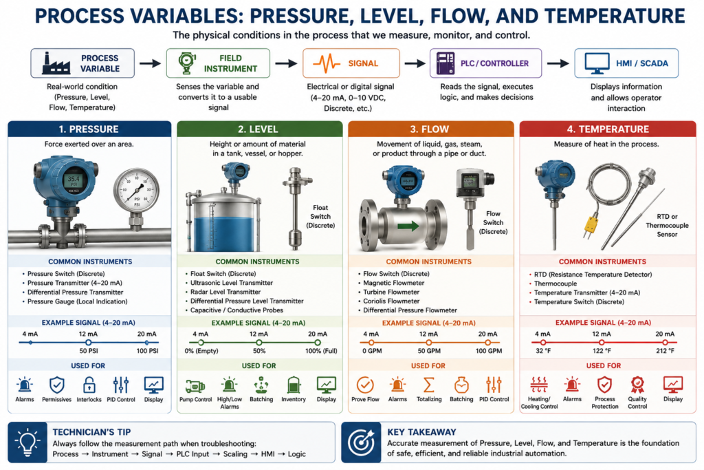
In industrial automation, a process variable is any physical condition that must be measured, monitored, displayed, controlled, or used in logic.
A PLC does not directly understand pressure, level, flow, or temperature. The PLC only understands electrical or digital signals. Instruments are used to convert real process conditions into signals the control system can read.
In simple terms:
A process variable is what is happening in the real world. Instrumentation converts that real-world condition into a usable signal for the PLC, HMI, or control system.
The book Lessons In Industrial Instrumentation introduces industrial instrumentation through real process examples such as boiler water level control, wastewater disinfection, chemical reactor temperature control, indicators, recorders, process switches, and alarms. These examples show how process variables are measured and used to control industrial systems.
Why Process Variables Matter
Every automatic system depends on information from the field.
For example:
- A pump may start or stop based on level.
- A valve may open based on pressure.
- A heater may turn off based on temperature.
- A dosing pump may run based on flow.
- An HMI alarm may activate when a process value goes outside normal limits.
Without accurate process variable measurement, the PLC may make the wrong decision.
A technician should always remember:
Bad process information creates bad control decisions.
Even if the PLC program is written correctly, the system can still fail if the instrument signal is incorrect, noisy, out of range, miswired, or incorrectly scaled.
The Four Main Process Variables
For automation technicians, the four most common process variables are:
| Process Variable | Common Instrument |
|---|---|
| Pressure | Pressure transmitter or pressure switch |
| Level | Level transmitter or level switch |
| Flow | Flowmeter or flow switch |
| Temperature | RTD, thermocouple, or temperature transmitter |
These variables are used in almost every industrial process.
1. Pressure
Pressure is the amount of force applied over an area.
In industrial systems, pressure is commonly found in:
- Compressed air systems
- Water lines
- Steam systems
- Hydraulic systems
- Pneumatic systems
- Tanks and vessels
- Pumps and filters
Common Pressure Instruments
| Instrument | Output Type | Example Use |
|---|---|---|
| Pressure Switch | Discrete ON/OFF | Low air pressure permissive |
| Pressure Transmitter | Analog 4–20 mA | Tank pressure display |
| Differential Pressure Transmitter | Analog 4–20 mA | Filter monitoring or flow measurement |
| Pressure Gauge | Local indication | Visual field reading |
Pressure Switch vs Pressure Transmitter
A pressure switch gives a discrete signal.
Example:
Pressure OK = ON
Low Pressure = OFF
A pressure transmitter gives an analog signal.
Example:
0–100 PSI = 4–20 mAThe PLC can use this pressure signal for:
- Low pressure alarms
- High pressure alarms
- Pump permissives
- Compressor monitoring
- Filter differential pressure
- Process control
- HMI display and trending
Technician Example: Low Air Pressure
A machine may require compressed air before it can start.
Example logic concept:
IF Air_Pressure_OK = TRUE
AND E_Stop_OK = TRUE
AND Guards_Closed = TRUE
THEN Machine_Start_Permissive = TRUE
If the air pressure switch is not made, the machine may not start.
The technician should check:
- Is the actual air pressure correct?
- Is the pressure switch adjusted correctly?
- Is the switch wired correctly?
- Is the PLC input turning ON?
- Is the HMI showing the correct permissive status?
2. Level
Level is the height or amount of material inside a tank, vessel, hopper, sump, or silo.
Level measurement is common in:
- Water tanks
- Chemical tanks
- Product tanks
- Sumps
- Hoppers
- Silos
- Mixing vessels
- Filling systems
Common Level Instruments
| Instrument | Output Type | Example Use |
|---|---|---|
| Float Switch | Discrete ON/OFF | High level or low level alarm |
| Ultrasonic Level Transmitter | Analog | Tank level measurement |
| Radar Level Transmitter | Analog or digital | Continuous level measurement |
| Differential Pressure Level Transmitter | Analog | Tank level based on liquid head pressure |
| Capacitive Level Sensor | Discrete or analog | Detect liquids or solids |
| Conductive Level Probe | Discrete | Detect liquid presence |
Level Switch vs Level Transmitter
A level switch detects a specific point.
Example:
Low Level Switch = ON/OFF
High Level Switch = ON/OFF
A level transmitter measures continuous level.
Example:
Tank Level = 0–100%The PLC can use level for:
- Pump start permissives
- Pump dry-run protection
- Tank high-level alarms
- Tank low-level alarms
- Filling control
- Batch control
- HMI tank graphics
- Inventory monitoring
Technician Example: Tank Level Permissive
A pump should not run if the tank level is too low.
Example logic concept:
IF Tank_Level > Minimum_Level
THEN Pump_Start_Allowed = TRUE
If the transmitter is reading incorrectly, the PLC may either prevent the pump from starting or allow the pump to run dry.
This is why level instrumentation is important for both production and equipment protection.
3. Flow
Flow is the movement of liquid, gas, steam, or product through a pipe or duct.
Flow measurement is common in:
- Water systems
- Chemical dosing
- Product transfer
- Air lines
- Steam systems
- CIP systems
- Cooling systems
- Filling machines
Common Flow Instruments
| Instrument | Output Type | Example Use |
|---|---|---|
| Flow Switch | Discrete ON/OFF | Prove flow after pump starts |
| Magnetic Flowmeter | Analog or digital | Conductive liquid flow |
| Turbine Flowmeter | Pulse or analog | Flow totalizing |
| Coriolis Flowmeter | Analog or digital | Mass flow and density |
| Vortex Flowmeter | Analog or digital | Steam or gas flow |
| Differential Pressure Flowmeter | Analog | Flow from pressure drop |
Flow Switch vs Flow Transmitter
A flow switch only proves flow exists.
Example:
Flow Detected = ON
No Flow = OFF
A flow transmitter measures how much flow is occurring.
Example:
0–100 GPM = 4–20 mAThe PLC can use flow for:
- Pump protection
- Flow alarms
- Batch totals
- Dosing control
- Production tracking
- CIP verification
- HMI display
- PID control
Technician Example: Pump Running but No Flow
A common industrial troubleshooting situation:
Pump Command = ON
Pump Feedback = ON
Flow Switch = OFF
This may indicate:
- Closed valve
- Clogged line
- Pump not primed
- Failed flow switch
- Wiring problem
- Pump rotating incorrectly
- Mechanical issue
- No product available
In PLC logic, this can become a fault:
IF Pump_Run_Command = TRUE
AND Flow_Proven = FALSE
FOR 10 Seconds
THEN No_Flow_Fault = TRUE
This is a good example of how instrumentation becomes part of machine protection.
4. Temperature
Temperature is the measurement of heat level in a process.
Temperature is common in:
- Ovens
- Tanks
- Heat exchangers
- Pasteurizers
- Freezers
- Chillers
- Motors
- Bearings
- Process lines
- Chemical reactors
Common Temperature Instruments
| Instrument | Output Type | Example Use |
|---|---|---|
| RTD | Resistance signal | Accurate temperature measurement |
| Thermocouple | Millivolt signal | High-temperature measurement |
| Temperature Transmitter | 4–20 mA | PLC temperature input |
| Temperature Switch | Discrete ON/OFF | High temperature alarm |
| Infrared Sensor | Analog or digital | Non-contact temperature measurement |
RTD vs Thermocouple
Two common temperature sensors are RTDs and thermocouples.
| Sensor | Basic Idea | Common Use |
|---|---|---|
| RTD | Resistance changes with temperature | Accurate industrial temperature measurement |
| Thermocouple | Small voltage changes with temperature | High-temperature or rugged applications |
A temperature transmitter can convert the RTD or thermocouple signal into a standard 4–20 mA signal for the PLC.
Example:
32–212 °F = 4–20 mAThe PLC can use temperature for:
- Heating control
- Cooling control
- High temperature alarms
- Low temperature alarms
- Product quality
- Process protection
- HMI display
- Data logging
Technician Example: Heater Control
A tank heater may be controlled based on temperature.
Example logic concept:
IF Tank_Temperature < Setpoint
AND Heater_Permissives_OK = TRUE
THEN Heater_Command = ON
The PLC depends on the temperature instrument to make the correct decision.
If the temperature reading is wrong, the process may overheat, underheat, or create a quality problem.
Process Variable to PLC Signal
The process variable must be converted into a signal the PLC can read.
Example:
Pressure → Pressure Transmitter → 4–20 mA → PLC Analog Input → Scaled PSIAnother example:
Level → Level Switch → 24 VDC Input → PLC Discrete Input → Low Level AlarmThe technician must understand what type of signal is being used.
Discrete Signal Example
Level Switch ON = Tank has level
Level Switch OFF = Low level condition
Analog Signal Example
4 mA = 0%
12 mA = 50%
20 mA = 100%
How Process Variables Are Used in PLC Logic
Process variables are not only displayed on the HMI. They are also used in control logic.
Common Uses
| Use | Example |
|---|---|
| Display | Show tank pressure on HMI |
| Alarm | High temperature alarm |
| Fault | No flow after pump start |
| Permissive | Minimum level required before pump starts |
| Interlock | High pressure shuts down pump |
| PID Control | Control valve position based on flow |
| Data Logging | Record temperature trend |
| Quality Check | Verify product stayed within temperature range |
Example: One Tank System
Imagine a simple tank system with a pump, valve, level transmitter, pressure transmitter, and flow switch.
Instruments
| Tag | Device | Purpose |
|---|---|---|
| LT-101 | Level Transmitter | Measures tank level |
| LSL-101 | Low Level Switch | Protects pump from dry-run |
| PT-101 | Pressure Transmitter | Measures discharge pressure |
| FSL-101 | Flow Switch Low | Proves flow after pump starts |
| TT-101 | Temperature Transmitter | Measures tank temperature |
PLC Logic Examples
Pump_Start_Allowed =
Tank_Level_OK
AND Low_Level_Switch_OK
AND No_Active_Faults
No_Flow_Fault =
Pump_Running
AND Flow_Not_Proven
AND Timer_DoneHigh_Temperature_Alarm =
Tank_Temperature > High_Temp_SetpointThis example shows why instrumentation is directly connected to automation logic.
Common Technician Troubleshooting Questions
When troubleshooting a process variable, ask:
Field Side
- Is the process actually at that condition?
- Is the instrument installed correctly?
- Is the impulse line, sensing port, or probe blocked?
- Is the instrument powered?
- Is the sensor damaged?
- Is the transmitter ranged correctly?
- Is the instrument calibrated?
Signal Side
- Is the PLC receiving the signal?
- Is the loop current correct?
- Is the 24 VDC signal present?
- Is the analog input stable?
- Is there electrical noise?
- Are the terminals tight?
- Is the shield grounded correctly?
PLC / HMI Side
- Is the raw input changing?
- Is the scaling correct?
- Are the engineering units correct?
- Is the HMI pointing to the correct tag?
- Are alarm setpoints correct?
- Is the logic using the correct condition?
Technician Mindset
A strong automation technician does not only replace parts.
A strong technician follows the complete measurement path:
Process Condition
→ Instrument
→ Wiring
→ Signal
→ PLC Input
→ Scaling
→ HMI Display
→ Logic Decision
This mindset prevents unnecessary part replacement and helps find the real root cause.
Key Takeaway
Pressure, level, flow, and temperature are the foundation of industrial process measurement.
These variables tell the automation system what is happening in the real world. Instruments convert those conditions into signals the PLC can read. The PLC then uses those signals for display, alarms, permissives, interlocks, faults, trends, and control.
For automation technicians, understanding process variables is one of the most important steps toward becoming strong in industrial instrumentation.
Final Thoughts
Industrial instrumentation can look complex, but the foundation is simple:
Measure the process correctly, send the signal correctly, scale it correctly, and use it correctly in the control system.
Once you understand pressure, level, flow, and temperature, the rest of instrumentation becomes easier to learn.
The next step is understanding the signals that carry this information from the field instrument to the PLC.