17. High-Speed Counters and Encoders
In the previous post, we covered standard PLC counters such as:
CTU = Count Up
CTD = Count Down
CTUD = Count Up / Count Down
Those counters work well for many basic counting applications.
But in real industrial automation, some signals are too fast for a normal PLC scan.
Examples:
Encoder pulses
High-speed product counting
Motor rotation feedback
Registration marks
Fast photoeye pulses
Indexing machine feedback
Position tracking
Speed measurement
For these applications, the PLC may need a high-speed counter.
In simple words:
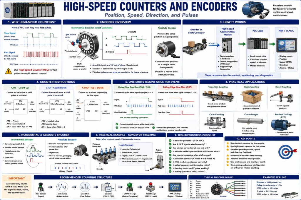
A high-speed counter counts fast pulses that may be too quick for normal ladder logic to detect reliably.Encoders are one of the most common devices connected to high-speed counters. An encoder electronically monitors the position of a rotating shaft and can provide information such as position, distance, and speed.
Why Normal PLC Counters May Not Be Enough
A normal PLC counter depends on the PLC scan.
The PLC must see the input transition from OFF to ON before it can count it.
But if the pulse is very fast, this can happen:
Pulse turns ON
Pulse turns OFF
PLC scan never sees it
Counter misses the event
This is especially possible with:
Very short pulses
High-speed conveyors
Fast rotating shafts
High-resolution encoders
Small products moving quickly
Input filters set too long
Long scan times
A regular CTU instruction is great when the PLC scan can reliably detect the signal. But when pulses arrive faster than the scan or input module can handle, you need high-speed hardware.
What Is a High-Speed Counter?
A high-speed counter, often called HSC, is a special counter designed to count fast input pulses independently of normal ladder scan timing.
Depending on the PLC platform, a high-speed counter may be:
Built into the PLC
Built into a compact controller
Part of a special input module
Part of a motion module
Part of a servo drive
Part of an encoder interface module
The key idea is:
The hardware captures fast pulses directly, then the PLC reads the accumulated count.This is different from normal ladder logic counting, where the counter depends heavily on scan timing.
High-Speed Counter vs Standard Counter
| Feature | Standard Counter | High-Speed Counter |
|---|---|---|
| Counts using | PLC scan / ladder logic | Dedicated hardware |
| Best for | Slow or moderate signals | Fast pulses |
| Example input | Box photoeye | Encoder A/B pulses |
| Risk | Can miss fast pulses | Captures pulses more reliably |
| Common use | Production count | Position, speed, distance |
| Hardware needed | Standard input module | HSC input/module or motion hardware |
What Is an Encoder?
An encoder is a feedback device used to measure motion.
It can measure:
Position
Distance
Speed
Direction
Rotation
Linear movement
Encoders are used in:
Conveyors
Servo systems
Indexing tables
Packaging machines
Robotics
Printing machines
Labeling systems
Filling machines
Cut-to-length systems
Material handling
An optical rotary encoder commonly uses a disk with slots or marks and a light source/receiver. As the shaft rotates, the light beam is interrupted and converted into electrical pulses.
Encoder Pulse Concept
Imagine an encoder connected to a conveyor shaft.
Every time the shaft rotates, the encoder produces pulses.
Example:
Encoder resolution = 1000 pulses per revolution
Shaft rotates 1 revolution
PLC/HSC counts 1000 pulses
If you know the conveyor roller circumference, you can convert pulses into distance.
Example:
1000 pulses = 1 roller revolution
1 roller revolution = 12 inches of belt travel
Therefore:
1000 pulses = 12 inches
This allows the PLC to track product movement more accurately than using only timers.
Why Encoders Are Better Than Timers for Position Tracking
A timer estimates position based on time.
Example:
Photoeye detects box
Wait 2 seconds
Fire reject solenoid
This may work only if conveyor speed is constant.
But if conveyor speed changes, the product will not be in the same position after 2 seconds.
An encoder tracks actual movement.
Example:
Photoeye detects box
Wait 1500 encoder pulses
Fire reject solenoid
This is usually better because the reject timing is based on real conveyor travel, not time.
Incremental Encoders
An incremental encoder generates pulses as it moves.
It provides relative movement, not absolute position by itself.
Simple concept:
More movement = more pulsesIncremental encoders provide relative position of the shaft. External electronics such as counters are required to accumulate the pulses in order to determine position, speed, and direction. They are commonly used for velocity control, point-to-point applications, and sequencing when position retention after power loss is not required.
Incremental Encoder Signals: A, B, and Z
Many incremental encoders provide three main signals:
A pulse
B pulse
Z pulse / Index pulse
A and B Pulses
The A and B signals are offset from each other.
This offset allows the controller to determine direction.
If A leads B → one direction
If B leads A → opposite direction
This is called quadrature.
By placing two sets of slots 90 degrees out of phase, direction can be determined; these two signals are known as A and B pulses. A single index or Z pulse may also be used to identify a home/reference position.
Z Pulse / Index Pulse
The Z pulse normally occurs once per revolution.
It is used for:
Home reference
Index reference
Position reset point
One pulse per revolution marker
Example:
Machine homes to sensor
Then uses Z pulse for precise reference
Quadrature Encoder Concept
Quadrature uses two signals:
Channel A
Channel B
These signals are shifted 90 degrees apart.
This lets the counter know both:
How many pulses occurred
Which direction the shaft moved
Example:
A before B = Forward
B before A = Reverse
This is very useful for applications where the shaft can move in both directions.
Absolute Encoders
An absolute encoder provides actual position information.
Unlike an incremental encoder, it does not only send pulses that must be accumulated.
Simple concept:
Absolute encoder = reports its actual positionAbsolute encoders provide the absolute angular position of the shaft. They are useful when position data must be retained after power loss and are used in applications such as packaging machines, robotics, lead/ball screw positioning, rotary tables, and pick-and-place systems.
Incremental vs Absolute Encoders
| Feature | Incremental Encoder | Absolute Encoder |
|---|---|---|
| Output | Pulses | Unique position value |
| Position after power loss | Usually must re-home | Position retained/known |
| Common signals | A, B, Z | Parallel, serial, networked data |
| Cost/complexity | Usually simpler | Usually more advanced |
| Common use | Speed, distance, relative position | Absolute position, robotics, axes |
| Needs counter? | Yes, for pulse accumulation | Depends on interface |
What Happens After Power Loss?
This is an important practical concept.
Incremental Encoder
After power loss:
The controller may lose position count.
The machine may need to home again.
Why?
Because the incremental encoder provides pulses relative to movement. If the controller loses the count, it no longer knows the actual position.
Absolute Encoder
After power loss:
The encoder can report its actual position again when power returns.This is why absolute encoders are preferred when position retention is important.
Encoder Resolution
Resolution means how many counts or pulses the encoder provides per revolution or per unit of travel.
Examples:
100 pulses per revolution
1024 pulses per revolution
2500 pulses per revolution
10000 pulses per revolution
Higher resolution means more pulses per movement.
That can improve position detail, but it also increases the pulse frequency that the counter must handle.
Example:
Higher resolution encoder
+ faster shaft speed
= higher pulse frequency
This is why you must verify that the input module or high-speed counter can handle the frequency.
Simple Encoder Math
Example:
Encoder = 1000 pulses per revolution
Roller circumference = 10 inches
Then:
1000 pulses = 10 inches
100 pulses = 1 inch
10 pulses = 0.1 inch
If the PLC counts 2500 pulses:
2500 pulses ÷ 100 pulses per inch = 25 inchesSo the conveyor moved 25 inches.
Speed Measurement Using Encoder Pulses
An encoder can also be used to measure speed.
Example:
Count pulses over a fixed time window.
Calculate pulses per second.
Convert to RPM or conveyor speed.
Example:
Encoder = 1000 pulses/rev
Measured pulses = 2000 pulses in 1 second
Speed = 2 revolutions/second
Speed = 120 RPM
This is a common method for speed feedback.
High-Speed Counter Applications
High-speed counters are used for:
Encoder position counting
RPM measurement
Conveyor tracking
Cut-to-length systems
Fast product counting
Registration mark detection
Packaging machine timing
Machine indexing
Length measurement
Speed feedback
Zero-speed detection
In motion systems, feedback sensors such as optical encoders, resolvers, and Hall effect devices return position or velocity information so the controller or drive can close position and velocity control loops.
Practical Example 1 — Conveyor Tracking
Requirement
Reject a bottle after it travels from inspection sensor to reject station.
Instead of:
Wait 2 secondsUse:
Wait 1800 encoder countsLogic concept:
Inspection_Fail detected
Store current encoder count
Target_Reject_Count = Current_Count + 1800
When Encoder_Count >= Target_Reject_Count
Fire Reject_Solenoid
This keeps the reject timing tied to actual conveyor travel.
Practical Example 2 — Cut-To-Length
Requirement
Cut material every 24 inches.
Encoder setup:
100 pulses = 1 inch
24 inches = 2400 pulses
Logic concept:
Start measuring material
When encoder count reaches 2400 pulses
Trigger cut
Reset count
Repeat
This is common in:
Tubing
Wire
Film
Labels
Paper
Metal strip
Packaging material
Practical Example 3 — Motor RPM Feedback
Requirement
Measure motor speed using encoder pulses.
Count pulses per second
Convert to revolutions per minute
Display RPM on HMI
Example:
Encoder = 1024 pulses/rev
Measured = 2048 pulses/sec
2048 / 1024 = 2 rev/sec
2 × 60 = 120 RPM
Practical Example 4 — Homing
A machine axis may need to establish a known position.
Typical homing sequence:
Move slowly toward home sensor.
When home sensor turns ON, continue until Z pulse.
Reset encoder count to 0.
Machine position is now referenced.
The index or Z pulse is used as a home/reference marker, especially with incremental encoders.
Practical Example 5 — Zero-Speed Detection
A high-speed counter can detect whether a shaft is moving.
Example:
If encoder count does not change for 2 seconds while motor command is ON,
generate zero-speed fault.
Possible causes:
Broken belt
Motor not turning
Encoder coupling loose
Encoder cable fault
Mechanical jam
Drive fault
Shaft slipping
This is a very useful diagnostic.
Wiring and Signal Types
Encoder wiring depends on the encoder type.
Common incremental encoder signals:
A
B
Z
A-not
B-not
Z-not
+V
0V
Shield
Many industrial encoders use differential line driver outputs for better noise immunity.
The encoder application summary recommends differential line driver outputs as the most reliable signal type for incremental encoders, and low-capacitance cable for longer cable runs to reduce signal distortion.
Encoder Troubleshooting
When an encoder or high-speed counter is not working, check:
Encoder power
0V common/reference
A/B signal wiring
Shield grounding
Cable damage
Loose connector
Encoder coupling
HSC module configuration
Counts increasing/decreasing
Direction bit
Input frequency limits
Noise from VFD/motor cables
Mechanical slipping
Homing sequence
Scaling math
Common Problem 1 — Count Does Not Change
Possible causes:
Encoder has no power
A/B wires disconnected
Wrong HSC channel
Bad module configuration
Broken encoder coupling
Input type mismatch
Cable damage
No common reference
Encoder shaft not rotating
Common Problem 2 — Count Changes in Wrong Direction
Possible causes:
A and B channels swapped
Direction setting inverted
Encoder mounted opposite direction
Mechanical direction changed
Scaling sign wrong
Fix may be:
Swap A/B channels if allowed by design
Change direction configuration
Invert direction in logic
Correct mechanical installation
Always follow machine documentation and site standards.
Common Problem 3 — Count Is Noisy or Jumping
Possible causes:
Electrical noise
Poor shield termination
Encoder cable near VFD motor leads
Loose connection
Wrong input type
Long cable with wrong cable type
Bad grounding
Damaged encoder
VFD motor wiring can generate electrical noise, and low-level control or feedback wiring should not be routed near high-power drive conductors because induced noise can disturb signals.
Common Problem 4 — Position Lost After Power Cycle
If the encoder is incremental, this may be expected.
Possible solutions:
Home the machine after power-up
Use Z index pulse
Use absolute encoder
Use battery-backed position system
Use drive-based position retention
If the application cannot tolerate losing position, consider absolute feedback.
Common Problem 5 — PLC Misses Pulses
Possible causes:
Using standard input instead of HSC
Input filter too slow
Pulse frequency too high
PLC scan too slow
Encoder resolution too high for hardware
Wrong voltage/output type
Fix:
Use high-speed counter input/module
Check max input frequency
Use correct encoder output type
Adjust input filtering
Verify wiring and shielding
High-Speed Counter and Ladder Logic
In many systems, the HSC hardware counts pulses independently.
The ladder logic then uses values such as:
Current_Count
Target_Count
Direction
Speed
Preset_Reached
Position_Error
Home_Complete
Example logic:
If Current_Count >= Target_Count
Then trigger output or move to next step
For high-speed control, avoid relying only on slow ladder logic when the action must happen with very precise timing. Some applications need hardware compare outputs or motion control hardware.
Automation Technician Notes
When troubleshooting encoder/HSC systems, ask:
Is this a standard counter or high-speed counter?
Is the pulse frequency within the module rating?
Is the encoder incremental or absolute?
Are A and B wired correctly?
Is the count increasing in the expected direction?
Is the Z pulse used for home?
Does position reset after power loss?
Is shielded cable used correctly?
Are encoder cables separated from VFD/motor power cables?
Is scaling from pulses to units correct?
Is the HMI displaying raw counts or engineering units?
A good technician does not only ask:
Is the encoder working?A good technician asks:
Is the controller receiving clean pulses, counting them correctly, and scaling them correctly?Best Practices
Use these habits:
Use high-speed inputs/modules for fast pulse signals.
Verify encoder resolution and max frequency.
Use shielded encoder cable.
Separate encoder wiring from VFD and motor power wiring.
Use differential line driver outputs when possible.
Document pulse-per-revolution and scaling math.
Use homing routines for incremental encoders.
Use absolute encoders when position must survive power loss.
Monitor raw counts and scaled position.
Use feedback faults for no-count or zero-speed conditions.
Key Terms
| Term | Meaning |
|---|---|
| High-Speed Counter | Hardware counter for fast pulses |
| Encoder | Feedback device for position, speed, or distance |
| Incremental Encoder | Encoder that generates pulses relative to movement |
| Absolute Encoder | Encoder that reports actual position |
| A/B Channels | Quadrature signals used for count and direction |
| Z Pulse | Index pulse used for home/reference |
| Quadrature | A/B signals 90 degrees out of phase |
| Resolution | Pulses per revolution or counts per unit |
| PPR | Pulses per revolution |
| HSC | High-speed counter |
| Homing | Referencing an axis to a known position |
| Scaling | Converting pulses into engineering units |
| Zero-Speed Detection | Detecting no motion when motion is expected |
Final Thoughts
High-speed counters and encoders are used when normal PLC counting is not fast or accurate enough.
A standard PLC counter is useful for basic product counting, but encoder pulses and fast position signals often require dedicated high-speed hardware.
Incremental encoders provide pulses that must be accumulated. Absolute encoders provide actual position. Quadrature A/B signals allow the controller to determine direction. The Z pulse can be used as a home reference.
For an Automation Technician, the key lesson is:
Standard counters count slow events.
High-speed counters count fast pulses.
Encoders provide motion feedback.
Once you understand high-speed counters and encoders, conveyor tracking, cut-to-length systems, speed feedback, indexing machines, and motion-related troubleshooting become much easier.