10. Going Online, Downloading, and Testing Logic in Studio 5000
After creating a Studio 5000 project, configuring tags, building ladder logic, and setting up I/O modules, the next major step is connecting to the controller.
This is where the PLC project moves from an offline file on your computer into a real controller that can control real equipment.
For an automation technician, this topic is extremely important because many troubleshooting tasks start with one question:
Can I connect to the PLC and go online?If you cannot communicate with the controller, you cannot monitor live logic, check tag values, test outputs, or troubleshoot the machine properly.
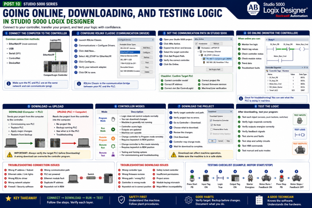
Rockwell’s Studio 5000 lab manual includes separate sections for connecting the computer to the controller, downloading the project, and testing the logic program. It specifically covers configuring an RSLinx Classic communication driver, downloading to the controller, switching the controller into Run Mode, and testing the program.
Offline vs Online
Before going deeper, it is important to understand the difference between offline and online.
Offline
Offline means you are working with the project file on your computer.
Example:
Machine_Project.ACDWhen offline, you can:
Create logic
Edit routines
Add tags
Configure I/O
Add modules
Create AOIs
Modify project structure
Save changes to the ACD file
But offline changes are not controlling the real machine until they are downloaded or applied online.
Online
Online means Studio 5000 is connected to the controller.
When online, you can:
Monitor live ladder logic
Watch tag values change
See controller status
Check module status
Test logic
Troubleshoot faults
Perform some online edits, depending on conditions
Simple explanation:
Offline = project file on your computer

Online = connected to the real PLC
Upload vs Download
This is one of the most important concepts in PLC work.
Many beginners confuse upload and download.
Download
Download means:
Computer → PLCYou are sending the project from your computer into the controller.
This is usually done when:
Commissioning a new controller
Replacing a controller
Loading a new project
Applying major offline changes
Restoring a backup
Upload
Upload means:
PLC → ComputerYou are pulling the current project from the controller into your computer.
This is usually done when:
You do not have the latest ACD file
You need to back up the running controller
You are checking what program is actually in the PLC
You are troubleshooting a system and need the live project
Important technician rule:
Download changes the PLC.

Upload reads from the PLC.
Be very careful with download. A wrong download can overwrite the controller project.
Before Connecting: Safety First
Before going online or downloading, remember that the PLC may control real equipment.
That equipment may include:
Motors
VFDs
Solenoids
Pneumatic cylinders
Hydraulic actuators
Heaters
Conveyors
Valves
Mixers
Robots
Packaging equipment
A download or controller mode change can affect production equipment.
Before working with a live controller:
Follow plant safety procedures.
Notify operations if required.
Understand what the PLC controls.
Know whether the machine is running.
Confirm if a download is allowed.
Understand the current controller mode.
Never force or toggle outputs without permission.
Use lockout/tagout when required.
Studio 5000 is a programming tool, but the result affects real machines.
Step 1 — Connect the Computer to the Controller
To go online, your computer must communicate with the controller.
Common connection methods include:
EtherNet/IP
USB
Serial, on older systems
ControlNet, in some systems
DeviceNet, in older distributed systems
Today, EtherNet/IP is very common for CompactLogix and ControlLogix systems.
Rockwell’s lab manual shows a basic network setup where the computer can be directly connected to one of the 1769-L36ERM Ethernet ports. It also lists Studio 5000 Logix Designer and RSLinx Classic as required tools for the lab.
EtherNet/IP Connection Basics
For EtherNet/IP communication, the computer and PLC must be on compatible network settings.
Example:
Computer IP: 192.168.1.10
PLC IP:      192.168.1.7
Subnet:      255.255.255.0
They must be able to communicate on the network.
Basic checks:
Is the Ethernet cable connected?
Are link lights active?
Is the computer IP in the correct subnet?
Can you ping the PLC?
Is the correct network adapter selected?
Is the PLC powered?
Is the Ethernet module healthy?
Is the IP address correct?
If the computer cannot see the PLC, Studio 5000 will not go online.
Step 2 — Configure RSLinx Classic
Studio 5000 uses communication software to find and communicate with controllers.
In many classic Allen-Bradley systems, that software is RSLinx Classic.
Rockwell’s lab manual explains that RSLinx Classic is used to configure the communication driver for talking to the CompactLogix processor. The lab specifically walks through launching RSLinx Classic and adding the AB_ETHIP EtherNet/IP driver.
Simple explanation:
RSLinx Classic = communication bridge between your computer and the PLCIn the lab, the driver used is:
AB_ETHIP — EtherNet/IP DriverThis driver browses EtherNet/IP devices on the network.
What Is a Communication Driver?
A communication driver tells your computer how to talk to the PLC network.
Examples:
EtherNet/IP driver
Ethernet Devices driver
USB driver
Serial DF1 driver
ControlNet driver
DeviceNet driver
If the wrong driver is configured, you may not see the controller.
If the correct driver is configured, you should be able to browse the network and find the controller.
Step 3 — Set the Communication Path in Studio 5000
After your computer can see the controller through RSLinx, Studio 5000 needs a path to that controller.
The communication path tells Studio 5000:
This is the controller I want to connect to.In Studio 5000, this is usually done through:
Who Active
Select controller
Set Project Path
Go Online
Download
Upload
A common mistake is having the wrong path selected.
Example:
Project is pointed to a lab PLC,
but you are trying to connect to a production PLC.
Always verify the correct controller before going online or downloading.
Technician Check: Confirm the Target PLC
Before going online or downloading, verify:
Controller model
Controller name
IP address
Slot number, if ControlLogix
Serial number, if needed
Project name
Machine or line name
For ControlLogix, also verify the controller slot.
Example:
Ethernet Module: Slot 1
Controller:      Slot 0
For CompactLogix, the path may be simpler, but you still need to confirm the correct IP address and controller.
Step 4 — Go Online
Going online connects Studio 5000 to the controller.
When online, you can monitor live logic.
You may see:
Rungs highlighting true/false
Tag values changing
Timer accumulators counting
Input bits turning on and off
Output commands energizing
Fault bits latching
Controller status indicators
This is one of the most powerful troubleshooting tools for a technician.
Example:
Start_PB turns green when pressed
Stop_OK remains true when healthy
Motor_Run_Cmd turns on when permissives are met
Motor_Fault turns on if feedback fails
Going online lets you see what the PLC is actually doing.
Online Status: Equal or Not Equal
When connecting, Studio 5000 may compare the offline project with the controller project.
Possible situations:
Offline project matches the controller.
Offline project does not match the controller.
Controller has a different project.
Controller has changes not in your file.
You need to upload.
You need to download.
If the offline file does not match the PLC, do not assume your laptop file is correct.
In real plant work, the running controller may have changes that are not in your saved ACD file.
Important rule:
The controller contains the logic currently running the machine.If unsure, upload first or verify with engineering/maintenance standards.
Step 5 — Download the Project
A download sends the project from your computer to the controller.
Rockwell’s lab manual includes a dedicated section for downloading the project from the computer to the controller, after the communication section.
Download is a serious action.
When you download:
The controller project may be overwritten.
The controller may transition modes.
Outputs may turn off depending on mode and system behavior.
The machine may stop.
The controller memory is updated with your project.
Never download casually in a production environment.
Before Downloading: Technician Checklist
Before downloading, verify:
[ ] Am I connected to the correct PLC?
[ ] Is this the correct ACD file?
[ ] Is this the correct controller type?
[ ] Is this the correct firmware revision?
[ ] Is production aware?
[ ] Is the machine in a safe state?
[ ] Are outputs safe to drop or change?
[ ] Is there a backup of the current running program?
[ ] Do I understand what changed?
[ ] Do I have permission to download?
This checklist protects the machine and the people around it.
Step 6 — Controller Modes
Logix controllers can operate in different modes.
Common modes include:
Program Mode
Run Mode
Remote Program
Remote Run
Remote Test
Program Mode
In Program Mode:
Logic is not controlling outputs normally.
The program can be downloaded.
The machine is generally not running under PLC logic.
Run Mode
In Run Mode:
The controller scans logic.
Outputs are updated.
The machine can operate.
Remote Run / Remote Program
Remote modes allow Studio 5000 to change controller mode from the software, depending on the keyswitch and permissions.
The lab manual includes a testing section where the controller is switched into Run Mode and the logic program is tested.
Step 7 — Test the Logic
After downloading and switching to Run Mode, test the logic carefully.
Rockwell’s lab manual includes a section specifically for testing the logic program after download and switching the controller into Run Mode.
Testing should confirm:
Inputs work correctly.
Logic responds correctly.
Outputs energize correctly.
Faults work correctly.
Alarms indicate correctly.
HMI commands work correctly.
Feedback confirms operation.
Stop and safety-related circuits behave correctly.
Testing is not only checking that the output turns on.
Testing means verifying the complete control behavior.
Basic Motor Test Example
For a simple motor start/stop circuit:
1. Press Start.
2. Verify DI_Start_PB turns ON.
3. Verify Motor_Run_Cmd turns ON.
4. Verify DO_Motor_Starter turns ON.
5. Verify motor starter energizes.
6. Verify FB_Motor_Running turns ON.
7. Release Start.
8. Verify seal-in keeps motor running.
9. Press Stop.
10. Verify Motor_Run_Cmd turns OFF.
11. Verify DO_Motor_Starter turns OFF.
12. Verify motor stops.
This confirms the path:
Input → Logic → Output → Field Device → FeedbackTesting Inputs
When testing inputs, verify both the field device and the PLC tag.
Example:
Field push button pressed
↓
Input module LED turns ON
↓
Raw input tag turns ON
↓
Alias tag turns ON
↓
Buffered input turns ON
↓
Logic condition becomes true
If the signal fails at any step, you know where to troubleshoot.
Testing Outputs
When testing outputs, verify both the PLC command and the field device.
Example:
Internal output command turns ON
↓
Output buffering turns ON
↓
Alias output turns ON
↓
Raw output tag turns ON
↓
Output module LED turns ON
↓
Voltage appears at terminal
↓
Field device energizes
↓
Feedback returns to PLC
This method prevents guessing.
Forcing vs Testing
Forcing is a powerful but dangerous tool.
A force can override normal logic behavior.
Forces may be used for commissioning or troubleshooting, but only with proper authorization and safety controls.
Important rule:
Forcing is not normal troubleshooting.
Forcing is controlled intervention.
Before forcing:
Know what the output controls.
Confirm the machine is safe.
Notify operations.
Follow plant procedure.
Remove forces when finished.
Document what was forced.
Never force outputs casually.
Common Connection Problems
1. Wrong IP Address
The computer is not on the same subnet as the PLC.
2. Wrong Driver
RSLinx driver is not configured correctly.
3. Bad Ethernet Cable
No link lights or intermittent connection.
4. Wrong Network Adapter
Laptop Wi-Fi or another Ethernet adapter is selected instead of the plant network adapter.
5. Firewall or Security Software
Communication may be blocked.
6. Wrong Controller Path
Studio 5000 is pointed to a different controller.
7. Firmware Version Mismatch
The project version does not match the controller firmware.
8. Controller Keyswitch Position
The keyswitch may prevent remote mode changes.
Common Download Problems
1. Wrong Controller Type
The project controller does not match the real controller.
2. Wrong Firmware Revision
Studio 5000 project revision does not match controller firmware.
3. Wrong Path
You selected the wrong controller.
4. Controller in Wrong Mode
Controller mode or keyswitch position may prevent download.
5. Safety-Locked Controller
Safety systems may require additional steps.
6. No Permission
Security may prevent download.
7. Unsaved or Unverified Logic
Project errors may prevent download.
Common Testing Mistakes
1. Testing Only the Output
Do not only check if the output turns on.
Check the full path:
Input → Logic → Output → Feedback2. Ignoring Feedback
A PLC command does not prove the field device moved or ran.
Use feedback when possible.
3. Not Testing Faults
A machine that runs but does not fault correctly is not fully tested.
4. Not Testing Stop Conditions
Always test stop, reset, permissives, and interlocks.
5. Leaving Forces Active
Forces must be removed and verified after testing.
6. No Backup
Always keep a backup before major changes.
Technician Troubleshooting Workflow
If you cannot go online:
1. Check physical Ethernet connection.
2. Check computer IP address.
3. Ping the PLC if allowed.
4. Open RSLinx Classic.
5. Verify the EtherNet/IP driver.
6. Browse for the controller.
7. Confirm controller IP and name.
8. Set the correct path in Studio 5000.
9. Try Go Online.
If you can go online but the machine does not work:
1. Check controller mode.
2. Check module faults.
3. Check input tags.
4. Check logic conditions.
5. Check output commands.
6. Check physical outputs.
7. Check field device feedback.
8. Check faults and alarms.
Programmer View
From a PLC programmer’s point of view, downloading and testing is the transition from design to reality.
A program should not be considered complete just because it compiles.
It must be tested against real machine behavior.
Good testing includes:
I/O checkout
Mode testing
Manual operation
Auto operation
Fault testing
Alarm testing
HMI testing
Interlock testing
Recovery testing
Power cycle testing, if applicable
This is where the programmer confirms that the logic does what the machine needs.
Automation Technician View
From a technician’s point of view, going online is one of the most important daily skills.
A technician should be comfortable with:
Opening the correct ACD file
Checking the communication path
Going online
Monitoring rungs
Watching tags
Checking module status
Understanding controller modes
Identifying mismatches
Avoiding unsafe downloads
Troubleshooting from input to output
This is what turns Studio 5000 from a programming tool into a troubleshooting tool.
Final Thoughts
Going online, downloading, and testing logic are core Studio 5000 skills.
For a PLC programmer, these steps bring the control project into the real controller.
For an automation technician, they provide access to the live logic needed to troubleshoot the machine.
Remember these key ideas:
Go Online = connect to the controller and monitor live logic.

Download = send the laptop project to the PLC.

Upload = read the project from the PLC into the laptop.

Run Mode = controller scans logic and updates outputs.

Testing = verify inputs, logic, outputs, feedback, faults, and alarms.
The most important technician rule is:
Never guess. Follow the signal path.Use Studio 5000 to verify each layer:
Field Device → I/O Module → Tag → Logic → Output → Field Device → FeedbackThat is how you troubleshoot safely and professionally.