9. Alias Tags: Making I/O Easier to Read
In Studio 5000 Logix Designer, I/O modules automatically create module-defined tags.
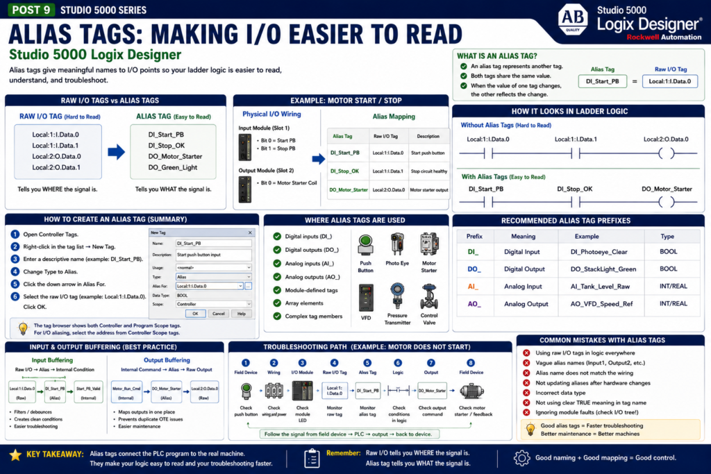
These tags are technically correct, but they are not always easy to read.
For example:
Local:1:I.Data.0
Local:1:I.Data.1
Local:2:O.Data.0
Local:2:O.Data.1
These tags tell you where the signal is located, but they do not clearly tell you what field device is connected.
That is where alias tags are very useful.
An alias tag lets you create a descriptive name for another tag. Rockwell’s Studio 5000 lab manual explains that an alias tag represents another tag, both tags share the same value, and when one value changes, the other reflects the change.
Simple definition:
Alias Tag = A readable name for another tagExample:
DI_Start_PB → Local:1:I.Data.0Now instead of using Local:1:I.Data.0 in the logic, you can use DI_Start_PB.
That makes the ladder logic much easier to understand.
Why Alias Tags Matter
From a technician point of view, alias tags make troubleshooting faster.
Compare these two rungs:
Local:1:I.Data.0     Local:1:I.Data.1     Local:2:O.Data.0
----] [----------------] [--------------------( )----
This works, but it is not very clear.
Now compare it with alias tags:
DI_Start_PB          DI_Stop_OK           DO_Motor_Starter
----] [----------------] [--------------------( )----
This is much easier to understand.
You can immediately see:
Start push button is required
Stop circuit must be OK
Motor starter output will energize
Good alias tags help the logic read like the machine.
Raw I/O Tags vs Alias Tags
Raw I/O tags are created by Studio 5000 based on the configured module.
Example:
Local:1:I.Data.0Meaning:
Local = local chassis/module group
1 = slot or module position
I = input data
Data.0 = input bit 0
Alias tags give that same point a readable name.
Example:
Local:1:I.Data.0 → DI_Start_PBComparison:
| Raw I/O Tag | Alias Tag | Meaning |
|---|---|---|
Local:1:I.Data.0 | DI_Start_PB | Start push button input |
Local:1:I.Data.1 | DI_Stop_OK | Stop circuit healthy |
Local:1:I.Data.2 | DI_Photoeye_Clear | Photoeye clear status |
Local:2:O.Data.0 | DO_Motor_Starter | Motor starter output |
Local:2:O.Data.1 | DO_Green_Light | Green pilot light output |
The raw tag identifies the hardware location.
The alias tag identifies the field device.
Both are useful, but for ladder readability, the alias is usually better.
Where Alias Tags Are Used
Rockwell’s lab manual lists several situations where aliases are useful: programming logic before wiring diagrams are complete, assigning a descriptive name to an I/O device, simplifying a complex tag, and giving a descriptive name to an array element.
In practical plant work, alias tags are commonly used for:
Digital inputs
Digital outputs
Analog inputs
Analog outputs
Module-defined tags
Array elements
Complex tag members
Examples:
DI_Motor_OL_OK → Local:1:I.Data.4
DO_Solenoid_A  → Local:2:O.Data.2
AI_Tank_Level  → Local:3:I.Ch0Data
AO_VFD_Speed   → Local:4:O.Ch0Data
This makes the project easier to read.
How Alias Tags Connect Logic to Real I/O
The Studio 5000 lab manual gives a practical example where ladder tags are aliased to points on a physical I/O module. It explains that this connects ladder logic to real-world I/O points.
That is the key idea.
Before aliasing, your ladder tag may just be an internal tag.
After aliasing, it points directly to a real input or output point.
Example:
Motor_Start → Local:1:I.Data.0
Motor_Stop  → Local:1:I.Data.1
Motor_Run   → Local:2:O.Data.0
Now the ladder logic is connected to the physical module points.
Simple Example: Motor Start/Stop
Assume your physical wiring is:
Input Module Slot 1
Bit 0 = Start push button
Bit 1 = Stop push button

Output Module Slot 2
Bit 0 = Motor starter coil
Raw I/O tags:
Local:1:I.Data.0
Local:1:I.Data.1
Local:2:O.Data.0
Alias tags:
DI_Start_PB       → Local:1:I.Data.0
DI_Stop_OK        → Local:1:I.Data.1
DO_Motor_Starter  → Local:2:O.Data.0
Ladder logic:
DI_Start_PB       DI_Stop_OK       DO_Motor_Starter
----] [--------------] [-----------------( )----
       |                              |
       | DO_Motor_Starter             |
       ----] [------------------------|
This is much clearer than using raw module tags directly.
Important Concept: Alias Tags Share the Same Value
An alias tag does not create separate memory.
It points to another tag.
So if this raw input turns on:
Local:1:I.Data.0 = 1Then the alias tag also shows:
DI_Start_PB = 1And if the raw input turns off:
Local:1:I.Data.0 = 0Then:
DI_Start_PB = 0They are two names pointing to the same value.
That is why alias tags are useful for readability without changing how the hardware signal works.
Alias Tags and Controller Scope
I/O module tags are created in controller scope. The lab manual notes that the tag browser for alias selection shows both Controller and Program Scope tags, and that for I/O aliasing you select the address from controller-scoped tags.
This is important because physical I/O is normally available globally in the controller.
Typical I/O alias tags are also often created in controller scope:
Controller Tags
 ├── DI_Start_PB
 ├── DI_Stop_OK
 ├── DI_Photoeye_Clear
 ├── DO_Motor_Starter
 └── DO_StackLight_Green
This allows multiple programs, HMI status logic, and diagnostic routines to reference the same physical I/O signal when needed.
Recommended Alias Tag Prefixes
Use clear prefixes so the tag tells you what type of signal it is.
| Prefix | Meaning | Example |
|---|---|---|
DI_ | Digital Input | DI_Start_PB |
DO_ | Digital Output | DO_Motor_Starter |
AI_ | Analog Input | AI_Tank_Level_Raw |
AO_ | Analog Output | AO_VFD_Speed_Ref |
This naming style helps technicians quickly identify the signal type.
Example:
DI_ = signal coming into the PLC
DO_ = signal going out of the PLC
AI_ = analog value coming into the PLC
AO_ = analog value going out of the PLC
Name What TRUE Means
For BOOL input aliases, the name should describe what the tag means when it is 1.
Good examples:
DI_Stop_OK
DI_EStop_OK
DI_Guard_Door_Closed
DI_Motor_OL_OK
DI_VFD_Ready
DI_Air_Pressure_OK
These names make the ladder logic easier to read.
Example:
DI_EStop_OK = 1This clearly means the E-stop circuit is healthy.
Poor example:
DI_EStopThat is not as clear because it does not tell you whether 1 means E-stop pressed or E-stop healthy.
A good tag name reduces confusion.
Alias Tags vs Internal Tags
Alias tags should not be used for everything.
They are great for naming physical I/O points, but internal logic should usually use normal base tags.
Alias Tags
Use for direct hardware references:
DI_Start_PB → Local:1:I.Data.0
DO_Motor_Starter → Local:2:O.Data.0
Internal Base Tags
Use for logic decisions:
Start_Request
Run_Permissive
Motor_Run_Cmd
Motor_Faulted
This creates a professional separation:
Alias tags = hardware layer

Internal tags = logic layer
Recommended Structure
A clean Studio 5000 program often follows this flow:
Raw I/O Tag → Alias Tag → Input Buffering → Logic → Output Buffering → Alias Output Tag → Raw Output TagExample:
Local:1:I.Data.0
       ↓
DI_Start_PB
       ↓
Start_PB_Valid
       ↓
Motor_Run_Cmd
       ↓
DO_Motor_Starter
       ↓
Local:2:O.Data.0
This may look like extra work, but it makes troubleshooting easier.
Input Alias Example
Raw input:
Local:1:I.Data.0Alias:
DI_Start_PBInput buffering:
DI_Start_PB → Start_PB_ValidLogic:
Start_PB_Valid AND Stop_OK AND No_Fault → Motor_Run_CmdThis separates the physical input from the internal decision-making logic.
Output Alias Example
Internal command:
Motor_Run_CmdOutput buffering:
Motor_Run_Cmd → DO_Motor_StarterAlias output:
DO_Motor_Starter → Local:2:O.Data.0This keeps the physical output mapping in one place.
If the motor does not start, the technician can check:
Motor_Run_Cmd
DO_Motor_Starter
Local:2:O.Data.0
Output module LED
Starter coil voltage
Motor feedback
That is a clean troubleshooting path.
Analog Alias Tags
Alias tags are not only for digital I/O.
They can also be used for analog channels.
Examples:
AI_Tank_Level_Raw → Local:3:I.Ch0Data
AI_Pressure_Raw   → Local:3:I.Ch1Data
AO_VFD_Speed_Ref  → Local:4:O.Ch0Data
Then you can create scaled engineering tags:
Tank_Level_Percent
Pressure_PSI
VFD_Speed_Percent
A clean analog structure may look like this:
AI_Tank_Level_Raw → Scaling Logic → Tank_Level_PercentThis makes it clear which tag is raw and which tag is scaled.
Troubleshooting with Alias Tags
Problem:
The PLC does not see the photoeye.
Step-by-step:
1. Check the photoeye LED in the field.
2. Check input voltage at the terminal.
3. Check the input module LED.
4. Monitor the raw input tag:
   Local:1:I.Data.2

5. Monitor the alias tag:
   DI_Photoeye_Clear

6. Check input buffering:
   Photoeye_Clear_Valid

7. Check the ladder logic using that signal.
This method tells you where the signal is being lost.
If the raw input is OFF, the issue is likely hardware, wiring, sensor, or module-related.
If the raw input is ON but the logic condition is OFF, the issue may be aliasing, buffering, debounce, or logic structure.
Common Mistake: Alias Name Does Not Match the Wiring
This is a big one.
Example:
DI_Start_PB → Local:1:I.Data.0But the real Start PB is wired to:
Local:1:I.Data.1Now the tag name is misleading.
The logic may look correct, but it points to the wrong physical input.
Always verify:
Electrical drawing
Panel terminal
I/O module point
Studio 5000 alias mapping
Field device label
Alias tags are powerful, but they must be mapped correctly.
Common Mistake: Using Raw I/O Tags in Logic
Avoid this when possible:
Local:1:I.Data.0     Local:1:I.Data.1     Local:2:O.Data.0
----] [----------------] [--------------------( )----
Better:
DI_Start_PB          DI_Stop_OK           DO_Motor_Starter
----] [----------------] [--------------------( )----
The second version is easier to troubleshoot, document, and explain.
Common Mistake: Vague Alias Names
Poor names:
Input_1
Output_2
Sensor_A
Motor
Switch
Better names:
DI_Box_In_Position
DO_Reject_Solenoid
DI_Low_Air_Pressure_OK
DO_Conveyor_Motor_Starter
DI_Guard_Door_Closed
A good alias tag should tell the technician what the field device does.
Common Mistake: Not Updating Aliases After Hardware Changes
If wiring changes, module slots change, or hardware is replaced, alias tags must be reviewed.
Example:
Old:
DI_Start_PB → Local:1:I.Data.0

New wiring:
Start PB moved to Local:1:I.Data.4
The alias must be updated:
DI_Start_PB → Local:1:I.Data.4Otherwise, the program may monitor the wrong input.
Best Practices for Alias Tags
Use these simple rules:
Use aliases for physical I/O points.
Use clear prefixes: DI_, DO_, AI_, AO_.
Name BOOL tags based on what TRUE means.
Keep alias mapping consistent with drawings.
Use descriptions for every important I/O point.
Avoid raw I/O tags in main machine logic.
Use input and output buffering for larger projects.
Verify aliases during commissioning.
These practices make programs easier to troubleshoot and maintain.
Technician Checklist for Alias Tags
When checking alias tags in Studio 5000:
[ ] Does the alias point to the correct raw I/O tag?
[ ] Does the alias name match the field device?
[ ] Does the tag description match the electrical drawing?
[ ] Does TRUE mean what the tag name says?
[ ] Is the raw input/output changing correctly?
[ ] Is the alias changing with the raw tag?
[ ] Is the alias used consistently in logic?
[ ] Are output aliases mapped in one output buffering routine?
This checklist can prevent many troubleshooting mistakes.
Final Thoughts
Alias tags are one of the most practical features in Studio 5000 Logix Designer.
They make raw I/O tags easier to read by giving them meaningful names.
Instead of working with:
Local:1:I.Data.0You can work with:
DI_Start_PBThat small change makes ladder logic much easier to understand.
For a PLC programmer, alias tags help create cleaner and more maintainable code.
For an automation technician, alias tags make troubleshooting faster because they connect the PLC software to the real field device.
Remember this simple idea:
Raw I/O tells you where the signal is.

Alias tag tells you what the signal is.
Use both when troubleshooting.