8. Configuring I/O Modules in Studio 5000
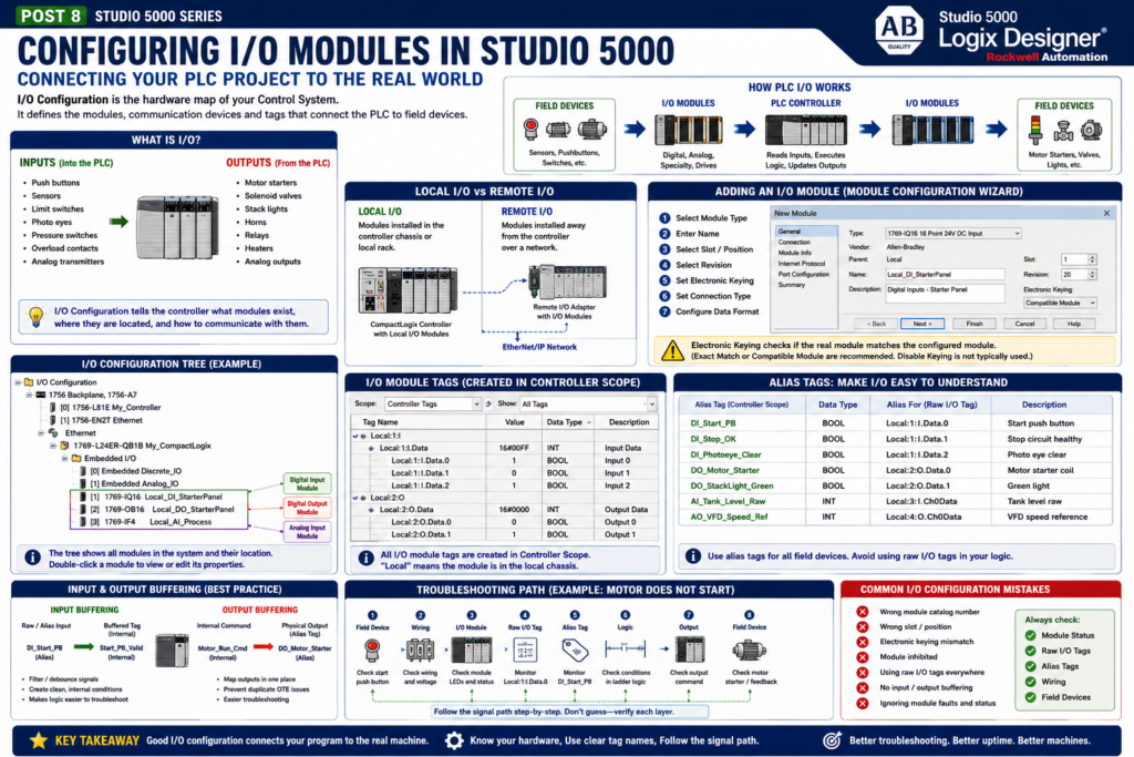
In Studio 5000 Logix Designer, the I/O Configuration is where the PLC project is connected to the real hardware.
This is where you define the modules, communication devices, input cards, output cards, analog cards, remote I/O adapters, drives, and other devices that the controller needs to communicate with.
For an automation technician, this area is very important because many machine problems are not caused by ladder logic. Sometimes the problem is in the I/O configuration, module status, wiring, communication path, or physical field device.
In simple terms:
I/O Configuration = The hardware map of the PLC systemRockwell’s Studio 5000 lab manual includes a full section on configuring I/O, including adding CompactLogix I/O, viewing I/O tags, and assigning alias tags.
Why I/O Configuration Matters
A PLC program cannot control real devices unless the controller knows what hardware is installed.
The I/O configuration tells the controller:
What modules exist
Where the modules are located
What type of module each one is
How the controller communicates with them
What data structure should be created
What input and output tags are available
Without proper I/O configuration, you may see:
Module faults
Communication errors
Wrong I/O data
Outputs not energizing
Inputs not updating
Download problems
Hardware mismatch warnings
That is why a good technician should understand the I/O tree, not only ladder logic.
What Is I/O?
I/O means Inputs and Outputs.
Inputs
Inputs are signals coming into the PLC.
Examples:
Push buttons
Selector switches
Photoelectric sensors
Proximity sensors
Limit switches
Pressure switches
Motor overload contacts
VFD ready signals
Valve feedback
Analog transmitters
Outputs
Outputs are signals going out of the PLC.
Examples:
Motor starter coils
VFD run commands
Solenoid valves
Stack lights
Horns
Relays
Heaters
Actuators
Analog speed references
Control valves
The PLC logic reads inputs, solves the program, and then commands outputs.
Inputs → PLC Logic → OutputsThis is the foundation of industrial control.
The I/O Configuration Folder
In the Controller Organizer, the I/O Configuration folder shows the hardware tree.
Depending on the system, you may see:
Local chassis
Ethernet network
Remote I/O adapters
Digital input modules
Digital output modules
Analog input modules
Analog output modules
VFDs
Servo drives
Safety modules
Specialty modules
In a small CompactLogix system, the I/O may be local to the controller.
In a larger ControlLogix system, you may see local chassis modules plus remote I/O racks over EtherNet/IP.
Local I/O vs Remote I/O
Local I/O
Local I/O is installed directly with the controller or in the same local chassis/backplane.
Example:
CompactLogix Controller
 ├── Local Digital Input Module
 ├── Local Digital Output Module
 └── Local Analog Input Module
The lab manual explains that modules that reside within the controller chassis are called Local.
Remote I/O
Remote I/O is installed away from the controller and connected over a network.
Example:
Controller
 └── EtherNet/IP
      └── Remote I/O Adapter
           ├── Digital Input Module
           ├── Digital Output Module
           └── Analog Input Module
Remote I/O is common in large machines, conveyor systems, tank farms, packaging lines, and process areas.
Adding an I/O Module
When you add an I/O module in Studio 5000, you normally go through a Module Configuration Wizard.
This wizard helps define the required module settings.
The lab manual explains that whenever an I/O module is added, the Module Configuration Wizard steps through the configuration needed for the module. It also notes that the configuration can be accessed later by double-clicking the module in the I/O Configuration folder or through the tag monitor/editor.
Typical settings include:
Module type
Catalog number
Name
Slot or position
Revision
Electronic keying
Connection type
Data format
Requested Packet Interval, depending on module
IP address, for network devices
For a technician, these settings matter because they must match the real hardware.
Software-Configured I/O
Modern Logix I/O modules are configured in software.
The lab manual explains that with the Logix family, I/O modules do not need DIP switches or jumpers for configuration. The I/O modules are software-configured, and the configuration is part of the controller program that is downloaded from the controller to the module.
This is important during maintenance.
If an I/O module fails and is replaced with the correct module, the controller can download the configuration to the replacement module, depending on the system setup and compatibility.
That makes replacement easier, but only if:
Correct module installed
Correct slot/position used
Correct catalog number selected
Correct revision/keying compatible
Network communication healthy
Electronic Keying
Electronic Keying is a safety and compatibility check between the module configured in the Studio 5000 project and the physical module installed in the system.
Simple explanation:
Electronic Keying checks if the real hardware matches the configured hardware.The lab manual explains that electronic keying determines what checks are performed before an I/O connection is made. It compares data such as vendor, product type, catalog number, major revision, and minor revision.
Common keying options include:
| Keying Option | Simple Meaning |
|---|---|
| Exact Match | Hardware must match the configured module very closely |
| Compatible Module | Hardware must be compatible with the configuration |
| Disable Keying | No keying check; not typically used |
The lab manual specifically notes that Disable Keying is not typically used.
Technician View: Why Electronic Keying Matters
Imagine you replace a failed input module.
If the new module is not compatible with the configured module, the controller may reject the connection.
This can create a module fault.
Possible causes:
Wrong catalog number
Wrong module type
Wrong firmware revision
Wrong slot
Wrong replacement part
Incompatible module
Electronic keying helps prevent the controller from communicating with the wrong hardware.
That protects the machine from improper operation.
Connection Type and Data Format
When configuring modules, you may also see settings such as Connection and Data Format.
The lab manual notes that input-only modules use Data, modules with outputs use Output, and the data format determines the data structure for the module tags.
Simple explanation:
Connection type = How the controller exchanges data with the module

Data format = What kind of tag structure Studio 5000 creates for that module
For most beginner troubleshooting, the key point is:
The I/O module configuration creates module-defined tags.Those tags are what you monitor in Studio 5000.
I/O Module Tags
When you configure an I/O module, Studio 5000 automatically creates tags for that module.
The lab manual explains that after I/O modules are configured, the I/O module tags can be viewed from Controller Tags and that all I/O module tags are created in Controller Scope.
You may see tags like:
Local:1:I
Local:1:I.Data
Local:2:O
Local:2:O.Data
Simple breakdown:
Local = module is local to the controller/chassis
1 or 2 = slot or module position
I = input data
O = output data
Data = actual input/output bits or values
Example:
Local:1:I.Data.0This may represent input bit 0 on the module in local slot 1.
Example:
Local:2:O.Data.3This may represent output bit 3 on the module in local slot 2.
Raw I/O Tags vs Alias Tags
Raw I/O tags work, but they can be difficult to read.
Example:
Local:1:I.Data.0That does not clearly tell you what field device is connected.
A better approach is to create an alias tag:
DI_Start_PB → Local:1:I.Data.0Now the logic is easier to understand.
Instead of seeing:
Local:1:I.Data.0You see:
DI_Start_PBThe lab manual includes a section specifically on assigning alias tags after viewing the CompactLogix I/O tags.
Why Alias Tags Are Important
Alias tags help connect the hardware address to the real machine signal.
Examples:
Local:1:I.Data.0 → DI_Start_PB
Local:1:I.Data.1 → DI_Stop_OK
Local:1:I.Data.2 → DI_Photoeye_Clear
Local:2:O.Data.0 → DO_Conveyor_Motor
Local:2:O.Data.1 → DO_StackLight_Green
This makes troubleshooting easier.
A technician can quickly understand:
What device is connected
What the PLC sees
What output is commanded
Where the signal maps to the hardware
Recommended I/O Naming Convention
A good I/O naming convention should clearly identify signal type and purpose.
Example:
| Prefix | Meaning | Example |
|---|---|---|
DI_ | Digital Input | DI_Start_PB |
DO_ | Digital Output | DO_Motor_Starter |
AI_ | Analog Input | AI_Tank_Level_Raw |
AO_ | Analog Output | AO_VFD_Speed_Ref |
For field troubleshooting, I like using names that explain what TRUE means.
Better:
DI_Stop_OK
DI_EStop_OK
DI_Guard_Door_Closed
DI_Overload_OK
DI_VFD_Ready
Instead of vague names like:
Stop_Button
EStop
Door
Overload
VFD
This avoids confusion between physical normally-closed wiring and PLC logic state.
Input Buffering
In more industrial programs, raw or alias inputs are often copied into internal logic tags.
Example:
DI_Start_PB → Start_PB_Valid
DI_Stop_OK → Stop_Circuit_OK
DI_Photoeye_Clear → PE_Clear_Valid
This is called input buffering.
Purpose:
Separate raw field signals from internal control logic
Add filtering or debounce if needed
Create clean internal conditions
Make troubleshooting easier
Example structure:
Input_Buffering routine:
DI_Start_PB → Start_PB_Valid
DI_Stop_OK → Stop_OK
DI_Photoeye_Clear → PE_Clear
Then the machine logic uses the clean internal tags.
Output Buffering
Output buffering does the opposite.
The program first creates internal command bits.
Then one routine maps those internal commands to physical outputs.
Example:
Motor_Run_Cmd → DO_Motor_Starter
Valve_Open_Cmd → DO_Valve_Open
Green_Light_Cmd → DO_StackLight_Green
Purpose:
Keep physical outputs in one place
Avoid duplicate OTE problems
Make output troubleshooting easier
Separate decision logic from hardware mapping
Recommended structure:
Output_Buffering routine:
Motor_Run_Cmd → DO_Motor_Starter
Valve_Open_Cmd → DO_Valve_Open
Alarm_Light_Cmd → DO_StackLight_Red
This is a very professional programming habit.
Technician Troubleshooting Path
When a field device is not working, follow the signal path.
For an Input Problem
Example: PLC does not see the start push button.
1. Check the physical push button.
2. Check control voltage.
3. Check wiring to input module.
4. Check input module LED.
5. Check raw I/O tag, such as Local:1:I.Data.0.
6. Check alias tag, such as DI_Start_PB.
7. Check input buffering logic.
8. Check where the tag is used in ladder logic.
For an Output Problem
Example: Motor starter does not energize.
1. Check internal command, such as Motor_Run_Cmd.
2. Check output buffering rung.
3. Check alias output, such as DO_Motor_Starter.
4. Check raw output tag, such as Local:2:O.Data.0.
5. Check output module LED.
6. Check voltage at the output terminal.
7. Check wiring to starter or relay.
8. Check starter coil, overload, safety circuit, or VFD input.
This method prevents guessing.
Module Status and Faults
The I/O Configuration tree can also show module status.
A module may be:
Running normally
Faulted
Inhibited
Not communicating
Wrong module
Wrong revision
Connection timed out
If an input or output is not working, always check the module status.
Do not assume the ladder logic is wrong.
Many real plant problems are caused by:
Network cable issue
Remote I/O adapter fault
Module inhibited
Wrong replacement module
Blown fuse
No field power
Bad terminal block
Loose wire
Bad sensor
Studio 5000 helps you separate logic issues from hardware issues.
Digital I/O vs Analog I/O
Digital I/O
Digital I/O is ON/OFF.
Examples:
Push button ON/OFF
Sensor detected/not detected
Motor starter ON/OFF
Solenoid energized/de-energized
Typical values:
0 = OFF
1 = ON
Analog I/O
Analog I/O uses a range of values.
Examples:
Tank level
Pressure
Temperature
Flow
Motor speed reference
Valve position command
Typical raw values may need scaling into engineering units.
Example:
Raw analog input → scaled tank level percentAnalog scaling will be a later topic, but for I/O configuration, remember:
Digital I/O = discrete bits
Analog I/O = numeric values
Common I/O Configuration Mistakes
1. Wrong Module Selected
The project must match the real module.
Wrong catalog number can cause module faults.
2. Wrong Slot or Position
If the module is configured in the wrong slot, the tags may not match the hardware.
3. Wrong Electronic Keying
Too strict or incompatible keying can prevent connection.
Too loose keying can allow unsafe or incorrect assumptions.
4. Module Inhibited
An inhibited module will not communicate normally.
Always check if the module is inhibited.
5. Raw I/O Used Everywhere
This makes logic harder to read.
Use alias tags for clarity.
6. No Input/Output Buffering
Directly using outputs in many routines can create confusion and duplicate output problems.
7. Ignoring Module Faults
Always check the I/O tree before blaming the logic.
Practical Example: Conveyor I/O
Imagine a simple conveyor system.
Digital Inputs
DI_Conv_Start_PB
DI_Conv_Stop_OK
DI_Conv_Photoeye_Clear
DI_Conv_Motor_OL_OK
DI_Conv_Motor_Run_FB
Digital Outputs
DO_Conv_Motor_Starter
DO_Conv_Green_Light
DO_Conv_Red_Light
DO_Conv_Horn
Internal Logic
Conv_Start_Request
Conv_Run_Permissive
Conv_Run_Cmd
Conv_Jam_Fault
Recommended Flow
Raw I/O → Alias Tags → Input Buffering → Logic → Output Buffering → Physical OutputsThis is a clean industrial structure.
PLC Programmer View
From a programmer’s perspective, I/O configuration should be clean and documented.
Good practices:
Use correct catalog numbers
Use meaningful module names
Use alias tags for field devices
Use clear descriptions
Use input buffering
Use output buffering
Keep physical output mapping in one place
Document module purpose
Use consistent naming conventions
Example module names:
Local_DI_StarterPanel
Local_DO_StarterPanel
RemoteIO_FillerHead_DI
RemoteIO_Conveyor_DO
This helps the next technician understand the system.
Automation Technician View
From a technician’s perspective, I/O configuration helps answer:
Is the PLC seeing the input?
Is the PLC commanding the output?
Is the module healthy?
Is the wiring correct?
Is the field device working?
Is this a logic issue or hardware issue?
When troubleshooting, always separate the problem into layers:
Field device
Wiring
I/O module
Network communication
PLC tag
Ladder logic
Output command
Feedback
This mindset makes troubleshooting much faster.
Final Thoughts
The I/O Configuration folder in Studio 5000 is the hardware map of the PLC project.
It tells the controller what modules exist and creates the I/O tags used by the logic.
For a PLC programmer, proper I/O configuration makes the project organized and maintainable.
For an automation technician, I/O configuration is essential for troubleshooting real-world machine problems.
Remember this simple flow:
Field Device → I/O Module → I/O Tag → PLC Logic → Output Tag → I/O Module → Field DeviceAnd remember:
Do not troubleshoot ladder logic only.
Always check the I/O configuration, module status, raw tags, alias tags, wiring, and field device.
A good technician understands both sides:
The software logic
AND
The physical hardware
That is where Studio 5000 becomes a powerful troubleshooting tool.