3. Creating Your First Studio 5000 Project
Creating Your First Studio 5000 Project
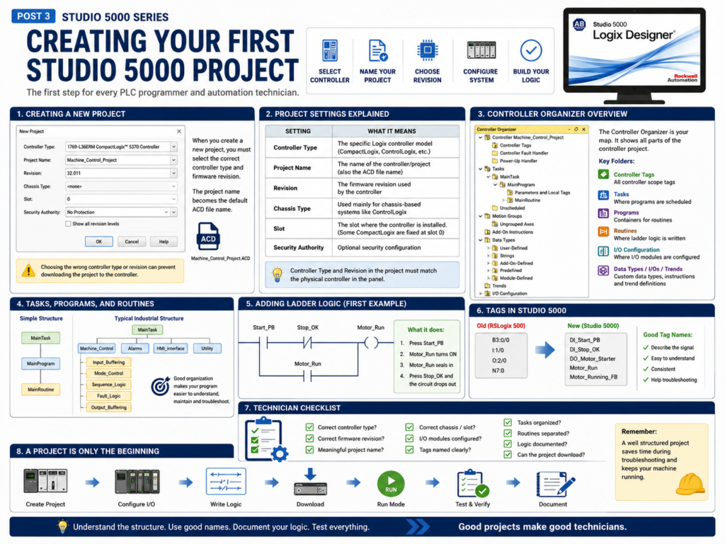
Creating a new project in Studio 5000 Logix Designer is one of the first practical skills every PLC programmer and automation technician should understand.
A Studio 5000 project is where the controller configuration, tags, I/O modules, tasks, programs, routines, and ladder logic are stored. In Allen-Bradley Logix systems, this project is saved as an ACD file.
For example:
Machine_Control_Project.ACD
Conveyor_Line_01.ACD
Tank_Farm_Controller.ACD
The ACD file is the main project file used by Studio 5000 Logix Designer.
Rockwell’s lab manual explains that when you create a new Studio 5000 project, the project name also becomes the default ACD file name.
Why This Matters for Technicians
As an automation technician, you may not create a brand-new PLC project every day. Most of the time, you may be opening an existing project to troubleshoot a machine.
However, understanding how a project is created helps you understand how the controller is structured.
When you open a Studio 5000 project, you should be able to recognize:
Controller type
Firmware revision
Controller name
Tasks
Programs
Routines
Controller tags
Program tags
I/O configuration
Communication path
This helps you troubleshoot with more confidence because you understand where everything comes from.
Starting a New Project
In Studio 5000, a new project starts by selecting the controller platform.
This is important because the controller type in the project must match the real controller hardware.
For example, you may create a project for:
1769-L36ERM CompactLogix
1756-L71 ControlLogix
5069-L306ER CompactLogix
1756-L8x ControlLogix
The lab manual shows an example where the user creates an offline project using a 1769-L36ERM CompactLogix controller. It also warns that choosing the wrong controller type or revision can prevent the project from downloading later.
That warning is important in real plant work.
If the project does not match the physical controller, you may run into download, compatibility, or firmware issues.
Important Project Settings
When creating a project, Studio 5000 asks for several important settings.
| Setting | What It Means |
|---|---|
| Controller Type | The specific Logix controller model |
| Project Name | The name of the controller/project |
| Revision | The firmware revision used by the controller |
| Chassis Type | Used mainly for chassis-based systems like ControlLogix |
| Slot | The slot where the controller is installed, if applicable |
| Security Authority | Optional security configuration |
The lab manual explains that the controller type defines whether the project uses ControlLogix, CompactLogix, or SoftLogix. It also explains that the revision is the firmware revision of the project, chassis type is not applicable for all controllers, and some CompactLogix controllers are fixed at slot zero.
Controller Type
The controller type must match the hardware.
For example, if the physical PLC is a CompactLogix 1769-L36ERM, the Studio 5000 project should be created for that same controller type.
If the controller type is incorrect, the software may not allow you to download the project.
Simple rule:
Physical PLC model = Studio 5000 controller typeAs a technician, always check the controller catalog number in the panel before assuming the project is correct.
Firmware Revision
The revision is also very important.
In Studio 5000, the project revision must be compatible with the controller firmware revision.
For example:
Controller firmware: v32
Studio 5000 project: v32
If the revision does not match, you may need to change the project revision, flash the controller firmware, or use the correct version of Studio 5000.
This is one reason why plants often keep multiple versions of Studio 5000 installed.
Technician note:
If you cannot open, download, or go online with a controller, always verify the controller firmware revision and Studio 5000 version.
Project Name
The project name should be clear and meaningful.
Avoid generic names like:
PLC_Project
Test
New_Project
Program1
Better names:
Line_3_Filler_Main
Freezer_Door_Control
TankFarm_CLX01
Conveyor_Cell_02
A good project name helps maintenance, engineering, and future troubleshooting.
A professional naming style should answer:
What machine or area does this controller belong to?Chassis and Slot
For ControlLogix, the controller is installed in a chassis. That means the project may need chassis and slot information.
Example:
Chassis: 1756-A10
Controller Slot: 0
Ethernet Module Slot: 1
Input Module Slot: 2
Output Module Slot: 3
For many CompactLogix controllers, the controller is not placed in a traditional ControlLogix chassis. Some CompactLogix controllers are fixed at slot zero.
The lab manual specifically notes that slot number does not apply to all controller types and gives CompactLogix as an example where the controller may be fixed at slot zero.
This difference matters when you troubleshoot I/O tags.
ControlLogix may show module paths based on chassis slots.
CompactLogix may show local modules in a more compact configuration.
What Happens After You Create the Project?
After creating the project, Studio 5000 opens the main project environment.
The most important area is the Controller Organizer.
This is the tree structure on the left side of the software where you can find the main components of the PLC project.
The lab manual explains that after creating the project, the Controller Organizer appears with the controller folder, and at that point there may be no I/O, tag database, or logic associated with the controller yet.
That is normal for a new project.
A new project starts mostly empty.
Then you build it by adding:
Tags
I/O modules
Ladder logic
Routines
Programs
Trends
AOIs
UDTs
Communication paths
Understanding the Controller Organizer
The Controller Organizer is one of the most important parts of Studio 5000.
It usually includes folders such as:
Controller Tags
Tasks
Motion Groups
Add-On Instructions
Data Types
Trends
I/O Configuration
The lab manual describes the Controller Organizer as a graphical representation of the controller file, with folders for tasks, motion groups, Add-On Instructions, data types, trends, and I/O configuration.
From a technician’s perspective, this is your map.
When troubleshooting, you use the Controller Organizer to find:
Where the logic is located
Where the tags are located
Where the I/O modules are configured
Where AOIs and UDTs are defined
Where trends may be stored
Tasks, Programs, and Routines
A Studio 5000 project is not just one long ladder file.
It is organized into:
Tasks → Programs → RoutinesA simple structure may look like this:
MainTask
 └── MainProgram
      └── MainRoutine
A more industrial structure may look like this:
MainTask
 └── Machine_Control
      ├── Input_Buffering
      ├── Mode_Control
      ├── Permissive_Logic
      ├── Interlock_Logic
      ├── Sequence_Logic
      ├── Fault_Logic
      ├── Alarm_Logic
      ├── Output_Buffering
      └── HMI_Status
This structure is important because it keeps logic organized.
A good PLC program should be easy to follow during a breakdown.
The Default Main Routine
When you create a new Studio 5000 project, you normally get a default task, program, and main routine.
This is where you can start adding ladder logic.
The lab manual shows the user expanding the MainProgram folder and opening the MainRoutine to begin adding ladder logic.
For a beginner, this is the first place to practice.
For a technician, this is often the first place to look when trying to understand a simple project.
Adding Ladder Logic
After opening the MainRoutine, you can add ladder instructions.
Common basic instructions include:
| Instruction | Meaning |
|---|---|
| XIC | Examine If Closed |
| XIO | Examine If Open |
| OTE | Output Energize |
| Branch | Parallel logic path |
| TON | Timer On Delay |
| CTU | Count Up |
| MOV | Move value |
The lab manual walks through adding a simple ladder rung using XIC, XIO, OTE, and a branch to create a basic motor start/stop style circuit.
This is a great first exercise because it teaches the foundation of PLC control logic.
Simple Example: Start/Stop Motor Logic
A basic motor seal-in circuit may look conceptually like this:
Start PB      Stop OK      Motor Run Command
----] [---------] [--------------------( )----
     |                              |
     |---- Motor Run Command -------|
The idea is simple:
- Press the Start push button.
- The motor run command turns on.
- The motor run command seals itself in.
- The motor keeps running after Start is released.
- Press Stop and the circuit drops out.
This is one of the most important ladder logic patterns for beginners.
Creating Tags
Studio 5000 uses tags instead of fixed memory addresses like older PLC platforms.
In older systems, you may see:
B3:0/0
N7:0
I:1/0
O:2/0
In Studio 5000, you use names like:
Motor_Start
Motor_Stop
Motor_Run
The lab manual explains that in Logix controllers there is no fixed numeric format like older traditional PLCs. Instead, tags are text-based names for memory areas, and this helps document ladder logic and organize data around the machine.
This is one of the biggest differences between RSLogix 500 and Studio 5000.
Why Tag Names Matter
Good tag names make troubleshooting easier.
Poor tag names:
Bit_1
Test_2
Output_A
Aux_3
Better tag names:
DI_Start_PB
DI_Stop_OK
DO_Motor_Starter
Motor_Run_Cmd
Motor_Running_FB
Motor_Fault
With clear tag names, another technician can understand the logic faster.
A tag should describe the signal’s purpose.
Basic Naming Convention Example
Here is a simple naming convention you can use:
DI_  = Digital Input
DO_  = Digital Output
AI_  = Analog Input
AO_  = Analog Output
CMD_ = Command
FB_  = Feedback
FLT_ = Fault
ALM_ = Alarm
Example:
DI_Start_PB
DI_Stop_PB
DI_Motor_OL
DO_Motor_Run
CMD_Motor_Start
FB_Motor_Running
FLT_Motor_Overload
ALM_Motor_Failed_To_Start
This style makes ladder logic easier to read.
Creating a Project Is Not the Same as Having a Working Machine
Creating the Studio 5000 project is only the beginning.
A complete project usually requires:
Correct controller selected
Correct firmware revision
I/O modules configured
Tags created
Logic written
Communication path configured
Project downloaded
Controller placed in Run mode
Logic tested
Field devices verified
Faults and alarms tested
Documentation added
This is why a PLC project should be tested carefully before being used in production.
Technician Checklist: New Studio 5000 Project
When reviewing or creating a Studio 5000 project, check:
[ ] Is the controller type correct?
[ ] Is the firmware revision correct?
[ ] Is the project name meaningful?
[ ] Is the chassis/slot configuration correct?
[ ] Are the I/O modules configured correctly?
[ ] Are tags named clearly?
[ ] Is the MainTask organized?
[ ] Are routines separated by function?
[ ] Is the ladder logic documented?
[ ] Can the project download to the controller?
[ ] Can the technician go online and monitor logic?
This checklist is simple, but it prevents many common mistakes.
Common Mistakes When Creating a Project
1. Selecting the Wrong Controller
This can prevent download or cause compatibility issues.
2. Selecting the Wrong Firmware Revision
This can prevent going online or downloading.
3. Using Poor Tag Names
This makes troubleshooting harder later.
4. Putting All Logic in One Routine
This may work for a small project, but it becomes difficult to troubleshoot in larger systems.
5. Not Configuring I/O Correctly
If the I/O tree does not match the real hardware, module faults or communication errors may occur.
6. Not Documenting the Logic
Comments and descriptions are important. They help the next technician understand the intent of the logic.
Practical Technician View
When you open a Studio 5000 project in the field, do not just look at the ladder logic.
First, understand the project structure:
What controller is this?
What machine or area does it control?
What task is running the logic?
What programs and routines exist?
Where are the controller tags?
Where is the I/O configuration?
Is the project online or offline?
Are there any controller or module faults?
This gives you context before you start troubleshooting.
Final Thoughts
Creating your first Studio 5000 project teaches more than just software navigation.
It teaches the foundation of how a Logix control system is organized:
Controller → Tasks → Programs → Routines → Tags → I/O → LogicFor a PLC programmer, this is the starting point for building a control system.
For an automation technician, this is the map used to understand and troubleshoot the machine.
A good Studio 5000 project should be:
Correctly configured
Clearly organized
Easy to read
Easy to troubleshoot
Documented
Matched to the real hardware
Once you understand how a project is created, it becomes much easier to understand existing PLC programs in the field.