1. What Is Studio 5000 Logix Designer?
What Is Studio 5000 Logix Designer?
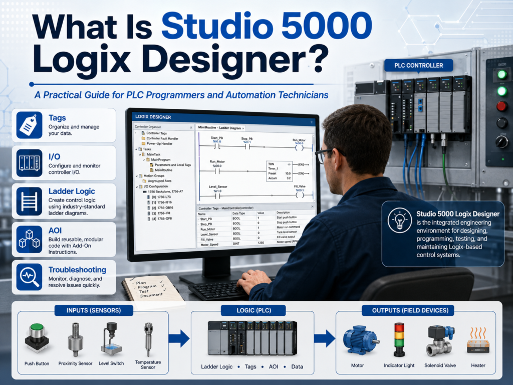
Studio 5000 Logix Designer is the main software used to program and configure Allen-Bradley Logix controllers, including ControlLogix and CompactLogix PLC/PAC systems.
For an automation technician or PLC programmer, Studio 5000 is not just a place to write ladder logic. It is the environment where you build the control system structure, create tags, configure I/O modules, communicate with the controller, download the program, test logic, monitor live values, and troubleshoot machine operation.
Rockwell’s lab material describes Logix Designer as the software used for programming and configuring Allen-Bradley ControlLogix and CompactLogix controllers. It also explains that Logix Designer supports different industrial control applications such as discrete, process, batch, motion, safety, and drive-based systems.
Why Studio 5000 Matters in Industrial Automation
In the field, a technician may open Studio 5000 for many reasons:
- Troubleshoot why a motor is not starting.
- Check if a PLC input is turning on.
- Verify if an output command is being sent.
- Monitor a timer, counter, fault bit, or machine state.
- Go online with a controller.
- Download or upload a PLC program.
- Add or modify logic during commissioning.
- Understand how the machine sequence works.
From a programming point of view, Studio 5000 is where the machine logic is created. From a technician point of view, it is where the machine behavior becomes visible.
That is why learning Studio 5000 is important for both roles.
A PLC programmer uses it to design and build control logic.
An automation technician uses it to understand, monitor, test, and troubleshoot the control system.
Studio 5000 vs Logix Designer
Many people say “Studio 5000” when they really mean “Logix Designer.”
The difference is simple:
Studio 5000 is the larger engineering environment.
Logix Designer is the application inside Studio 5000 used to program Logix controllers.
Rockwell describes the Studio 5000 environment as a common engineering and design environment, with Logix Designer being the first element used to program Logix 5000 controllers. The manual also explains that Logix Designer is the rebranded version of RSLogix 5000.
In simple terms:
Studio 5000 = Engineering environment
Logix Designer = PLC programming application
So when someone says:
“Open Studio 5000 and check the PLC logic.”
They usually mean:
“Open Logix Designer and go online with the controller.”
What Controllers Use Studio 5000?
Studio 5000 Logix Designer is used with the Logix family of controllers, including:
- ControlLogix
- CompactLogix
- GuardLogix
- Compact GuardLogix
- SoftLogix / Emulate platforms, depending on version and application
The Add-On Instruction manual identifies Logix 5000 controllers as platforms based on the Logix 5000 operating system, including ControlLogix, GuardLogix, CompactLogix, Compact GuardLogix, SoftLogix, and Emulate 5570.
For most technicians in a plant, the two most common platforms are:
| Platform | Common Use |
|---|---|
| ControlLogix | Large systems, process areas, motion, high-speed control, plant-wide architecture |
| CompactLogix | Smaller machines, packaging equipment, standalone systems, local machine control |
Rockwell’s lab manual describes ControlLogix as a high-performance platform for multidiscipline control such as sequential, process, drive, and motion applications. CompactLogix is described as a smaller machine-level control platform suitable for small to medium systems.
What Can You Program in Studio 5000?
Studio 5000 supports multiple IEC 61131-3 programming languages.
The most common ones are:
| Language | Common Use |
|---|---|
| Ladder Diagram | Discrete logic, motors, sensors, permissives, interlocks |
| Function Block Diagram | Process control, analog logic, PID, flow/pressure/temperature control |
| Structured Text | Calculations, loops, data handling, advanced logic |
| Sequential Function Chart | Step-based sequences, machine phases, batch-type processes |
For technicians, ladder logic is usually the first and most important language to learn because it visually represents industrial control logic. The lab manual confirms that Logix Designer provides Ladder Logic, Structured Text, Function Block Diagram, and Sequential Function Chart editors.
Why Ladder Logic Is Still Important
Even though Studio 5000 supports advanced programming languages, ladder logic is still heavily used in industry because it is easy to troubleshoot.
A technician can look at a rung and see:
Start PB + Stop OK + Permissive OK = Motor Run CommandThat makes ladder logic very useful for:
- Motor control
- Solenoid valves
- Conveyor logic
- Safety status monitoring
- Sensor validation
- Permissives
- Interlocks
- Faults and alarms
- Machine sequence control
In the field, ladder logic helps answer the most important troubleshooting question:
“What condition is preventing this output from turning on?”
Important Areas Inside Studio 5000
When you open a Studio 5000 project, the Controller Organizer is one of the most important areas.
This is where you find the main structure of the PLC program.
Common folders include:
| Area | Purpose |
|---|---|
| Controller Tags | Global tags available to the controller |
| Tasks | Defines when programs execute |
| Programs | Organizes logic by machine area or function |
| Routines | Contains ladder, structured text, function block, or SFC logic |
| Add-On Instructions | Custom reusable instructions |
| Data Types | User-defined and predefined data structures |
| Trends | Tools for monitoring values over time |
| I/O Configuration | Hardware modules and communication setup |
The lab manual shows the Controller Organizer as the graphical tree that contains the controller file, tasks, motion groups, Add-On Instructions, data types, trends, and I/O configuration.
Studio 5000 Uses Tags, Not Old-Style Addresses
One major difference between Studio 5000 and older PLC platforms is the use of tag-based addressing.
In older PLCs, you may see addresses like:
N7:0
B3:0/0
I:1/0
O:2/0
In Studio 5000, you normally use descriptive tag names like:
Motor_Start_PB
Motor_Stop_PB
Motor_Run_Cmd
Conveyor_Running_FB
Tank_Level
Door_Open_LS
This makes the logic easier to read and troubleshoot.
Instead of asking:
“What is B3:0/4?”
You can read the tag and understand the purpose immediately:
“Motor_Run_Command.”
The lab manual explains that Logix controllers do not use a fixed numeric memory format like older PLCs; instead, tags are text-based names for areas of memory and help document ladder code.
Technician View: How Studio 5000 Helps Troubleshooting
From a troubleshooting perspective, Studio 5000 helps you follow the machine control path:
Field Device → PLC Input → Logic Condition → Output Command → Field Device ResponseFor example, if a conveyor does not start, you can check:
- Is the start push button input turning on?
- Is the stop circuit healthy?
- Are all permissives true?
- Is there an active fault?
- Is the motor output command turning on?
- Is the starter or VFD receiving the command?
- Is motor feedback returning to the PLC?
This is why Studio 5000 is powerful. It connects the electrical panel, PLC logic, field devices, and troubleshooting process in one environment.
Programmer View: How Studio 5000 Helps Build Machines
From a programming perspective, Studio 5000 helps organize logic into a professional structure.
A well-designed project may include:
MainTask
 └── MainProgram
      ├── Input_Buffering
      ├── Mode_Control
      ├── Permissive_Logic
      ├── Interlock_Logic
      ├── Sequence_Logic
      ├── Fault_Logic
      ├── Alarm_Logic
      ├── Output_Buffering
      └── HMI_Status
This structure makes the program easier to read, maintain, and troubleshoot.
A professional PLC program should not be only “logic that works.” It should be logic that another technician can understand during a breakdown.
Where Add-On Instructions Fit In
Add-On Instructions, usually called AOIs, are one of the more advanced features in Studio 5000.
An AOI is a custom instruction created by the programmer. It can package repeated logic into one reusable block.
For example, instead of writing the same motor logic 20 times, you could create a motor AOI and reuse it for each motor.
The AOI manual explains that Add-On Instructions allow programmers to create new instructions for commonly used logic, provide a common interface, document the instruction, and reuse control algorithms across projects.
A simple motor AOI may include:
Inputs:
- Start_Command
- Stop_Command
- Motor_Feedback
- Overload_OK
- Reset

Outputs:
- Run_Command
- Running
- Faulted
- Alarm
This helps make large programs cleaner and more consistent.
Simple Example: Motor Control in Studio 5000
A basic motor circuit in Studio 5000 may look conceptually like this:
Start PB     Stop OK     No Fault
----] [--------] [---------] [----------------( Motor_Run_Cmd )
       |                                  |
       |---- Motor_Run_Cmd --------------|
This is called a seal-in circuit.
The idea is simple:
- Press Start.
- The motor run command turns on.
- The run command seals itself in.
- Press Stop or get a fault, and the command turns off.
This type of logic is one of the first things a technician should understand before moving into more advanced topics like UDTs, AOIs, machine states, and structured programming.
Common Mistake: Thinking Studio 5000 Is Only for Programming
Studio 5000 is not only for writing code.
In real industrial work, Studio 5000 is also used for:
- Troubleshooting
- Commissioning
- Testing I/O
- Monitoring machine states
- Checking fault logic
- Verifying HMI tags
- Confirming controller communication
- Understanding machine sequences
- Supporting VFDs, motion, safety, and process systems
A technician may not create a full PLC project from zero every day, but they will often need to open an existing project and understand what the logic is doing.
That is a very important skill.
What a Technician Should Focus On First
When learning Studio 5000, do not try to learn everything at once.
Start with the fundamentals:
- Understand the Controller Organizer.
- Learn how Tasks, Programs, and Routines are organized.
- Understand tags.
- Learn basic ladder instructions: XIC, XIO, OTE, OTL, OTU, TON, CTU, MOV.
- Learn how to monitor live logic.
- Learn how PLC inputs and outputs are represented.
- Learn how to troubleshoot from input to logic to output.
- Learn how faults, alarms, permissives, and interlocks are structured.
After that, you can move into:
- UDTs
- AOIs
- Produced/Consumed tags
- Periodic tasks
- Add-On Profiles
- Motion
- Safety logic
- Advanced diagnostics
Final Thoughts
Studio 5000 Logix Designer is one of the most important tools for Allen-Bradley PLC programming and troubleshooting.
For a PLC programmer, it is where the control system is designed.
For an automation technician, it is where the machine logic becomes visible.
Learning Studio 5000 is not just about learning software buttons. It is about learning how industrial machines think:
Inputs → Logic → Outputs → Feedback → Faults → Alarms → Machine StateOnce you understand that flow, Studio 5000 becomes much easier to learn.
This series will build from the basics into more advanced topics like tags, I/O configuration, online edits, trends, UDTs, periodic tasks, and Add-On Instructions.
The goal is simple:
To understand Studio 5000 from the practical point of view of a PLC programmer and automation technician.