6. Scaling Analog Inputs in a PLC
From Raw Counts to Engineering Units
In industrial automation, a PLC does not automatically understand pressure, level, flow, temperature, or weight.
The PLC receives an electrical signal from the field instrument. That signal may be 4–20 mA, 0–10 VDC, an RTD signal, a thermocouple signal, or a digital value from a networked device.
But inside the PLC, that signal is usually represented as a raw number.
That raw number must be converted into a real process value.
This conversion is called scaling.
In simple terms:
Scaling is the process of converting a raw PLC input value into engineering units that technicians, operators, and control logic can understand.
Example:
Raw Analog Input → Scaling Logic → PSI, GPM, °F, %, gallons, poundsThe book Lessons In Industrial Instrumentation includes analog signal calculations, 4–20 mA relationships, graphical interpretation of signal ranges, per-unit thinking, and PLC analog input scaling examples, which are all foundational for understanding how field signals become usable process values in a control system.
Why Analog Scaling Matters
Analog scaling is important because the PLC logic, HMI, alarms, trends, and control decisions depend on the scaled value.
For example, a pressure transmitter may send:
4–20 mA = 0–100 PSIBut the PLC analog input card may see that signal as:
Raw count = 0 to 32767The technician and operator do not want to see:
Raw Input = 16384They want to see:
Pressure = 50 PSIThat is the purpose of scaling.
The Basic Signal Path
A typical analog signal path looks like this:
Process Variable
→ Transmitter
→ 4–20 mA Signal
→ PLC Analog Input Card
→ Raw Count
→ Scaling Logic
→ Engineering Unit Value
→ HMI Display / PLC Logic
Example:
Tank Pressure
→ Pressure Transmitter
→ 12 mA
→ PLC Analog Input
→ Raw Count
→ Scaling
→ 50 PSI
→ HMI Display
The PLC does not “know” that 12 mA means 50 PSI until the program scales it correctly.
What Are Engineering Units?
Engineering units are the real-world units used to describe the process.
Examples:
| Process Variable | Engineering Unit |
|---|---|
| Pressure | PSI, bar, kPa |
| Level | %, gallons, inches, feet |
| Flow | GPM, LPM, CFM |
| Temperature | °F, °C |
| Weight | lb, kg |
| pH | pH |
| Conductivity | µS/cm |
A good PLC program should convert raw values into engineering units before using them in alarms, permissives, interlocks, and HMI displays.
Raw Counts vs Engineering Units
A PLC analog input module converts the electrical signal into a digital number.
This number is often called:
- Raw count
- Raw input
- ADC value
- Analog input count
- Digital representation
Example:
Raw Input = 0 to 32767But raw counts are not meaningful to most operators or technicians.
A scaled value is easier to understand:
Raw Input 16384 = 50 PSISimple Example: Pressure Transmitter
Instrument:
PT-101
Range: 0–100 PSI
Output: 4–20 mA
Signal relationship:
| Pressure | Signal |
|---|---|
| 0 PSI | 4 mA |
| 25 PSI | 8 mA |
| 50 PSI | 12 mA |
| 75 PSI | 16 mA |
| 100 PSI | 20 mA |
PLC scaling result:
| Raw / Signal Condition | Scaled Value |
|---|---|
| 4 mA | 0 PSI |
| 12 mA | 50 PSI |
| 20 mA | 100 PSI |
The HMI should display:
Tank Pressure: 50 PSInot:
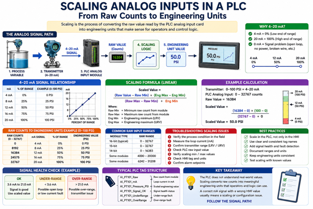
Analog Raw Count: 16384The Scaling Formula
Most analog scaling follows a linear relationship.
The basic formula is:
Scaled Value =
((Raw Value - Raw Min) × (Engineering Max - Engineering Min)
÷ (Raw Max - Raw Min))
+ Engineering Min
That looks heavy at first, but the idea is simple:
Where is the raw value between raw minimum and raw maximum?
Then convert that same percentage into engineering units.
Example With Raw Counts
Let’s say the PLC analog input range is:
Raw Min = 0
Raw Max = 32767
The transmitter range is:
Engineering Min = 0 PSI
Engineering Max = 100 PSI
If the raw value is:
Raw Value = 16384That is about 50% of the raw range.
So the scaled value is about:
Scaled Value = 50 PSIExample Table: 0–32767 Raw Counts to 0–100 PSI
| Raw Count | Percent of Range | Pressure |
|---|---|---|
| 0 | 0% | 0 PSI |
| 8192 | 25% | 25 PSI |
| 16384 | 50% | 50 PSI |
| 24575 | 75% | 75 PSI |
| 32767 | 100% | 100 PSI |
This is the basic concept behind analog input scaling.
Important: Module Raw Range May Be Different
Not every PLC analog card uses the same raw range.
Depending on the manufacturer, module, and configuration, the raw range may be different.
Examples:
| Possible Raw Range | Example |
|---|---|
| 0–32767 | Common generic example |
| 4000–20000 | Sometimes used to represent 4–20 mA directly |
| 6242–31208 | Example style used by some analog modules |
| 0–16383 | 14-bit module range |
| Floating-point engineering units | Some smart modules can scale internally |
This is why the technician should always check:
- Analog module manual
- Channel configuration
- PLC program scaling
- Engineering range
- Transmitter range
Never assume all analog inputs use the same raw count range.
LRV and URV
In instrumentation, two very important terms are:
| Term | Meaning |
|---|---|
| LRV | Lower Range Value |
| URV | Upper Range Value |
Example:
LRV = 0 PSI
URV = 100 PSI
That means:
4 mA = 0 PSI
20 mA = 100 PSI
Another example:
LRV = 32 °F
URV = 212 °F
That means:
4 mA = 32 °F
20 mA = 212 °F
For scaling to be correct, the PLC engineering range must match the transmitter range.
Common Scaling Mistake
A very common problem is when the transmitter range and PLC scaling do not match.
Example:
Transmitter Range: 0–150 PSI
PLC Scaling: 0–100 PSI
In this case, the loop current may be correct, but the HMI value will be wrong.
The technician may measure the correct mA signal and still see an incorrect pressure on the HMI.
That means the problem is not the transmitter.
The problem may be:
- Wrong scaling
- Wrong engineering range
- Wrong HMI tag
- Wrong analog card configuration
- Wrong transmitter range entered in the PLC
Example: Correct mA but Wrong HMI Value
Problem:
Field gauge = 75 PSI
Loop current = 12 mA
HMI = 50 PSI
At first, this may look confusing.
But if the transmitter is ranged:
0–150 PSI = 4–20 mAthen:
12 mA = 75 PSIIf the PLC scaling is incorrectly set to:
0–100 PSIthen:
12 mA = 50 PSISo the HMI is wrong because the scaling does not match the transmitter range.
Scaling 4–20 mA Directly
Sometimes technicians think in mA instead of raw counts.
For a 4–20 mA signal:
| mA | Percent |
|---|---|
| 4 mA | 0% |
| 8 mA | 25% |
| 12 mA | 50% |
| 16 mA | 75% |
| 20 mA | 100% |
Example:
Transmitter Range: 0–200 gallonsThen:
| mA | Level |
|---|---|
| 4 mA | 0 gallons |
| 12 mA | 100 gallons |
| 20 mA | 200 gallons |
This is a good way to troubleshoot quickly in the field.
Scaling in PLC Logic
In a professional PLC program, analog handling should be organized clearly.
A good structure may look like this:
Raw Input
→ Scaled Engineering Value
→ Signal Health Check
→ Alarm Logic
→ HMI Display
→ Control Logic
Example tags:
AI_PT101_Raw
AI_PT101_mA
AI_PT101_Pressure_PSI
AI_PT101_Signal_OK
AI_PT101_UnderRange
AI_PT101_OverRange
PT101_High_Alarm
PT101_HighHigh_Fault
This makes troubleshooting much easier.
Studio 5000 Style Concept
In Studio 5000, you may use different methods to scale an analog input depending on the system.
Common approaches include:
- Module configuration scaling
- SCP-style add-on instruction
- CPT instruction
- AOI for analog scaling
- Structured Text calculation
- Function Block scaling
- HMI-side scaling, although PLC-side is usually better for logic
A clean industrial approach is to scale analog values in the PLC and send engineering units to the HMI.
That way, alarms, permissives, interlocks, trends, and displays all use the same trusted value.
RSLogix 500 Style Concept
In RSLogix 500 / SLC-style programming, many technicians use an SCP instruction.
SCP means:
Scale with ParametersTypical SCP parameters:
Input
Input Min
Input Max
Scaled Min
Scaled Max
Output
Example:
Input: Analog_Raw
Input Min: 0
Input Max: 32767
Scaled Min: 0
Scaled Max: 100
Output: Pressure_PSI
This converts raw analog input into engineering units.
PLCLogix / Simulator Style Concept
In PLC simulators, the exact analog input behavior may be different from real hardware.
But the concept is the same:
Raw Value → Scaling → Engineering UnitsWhen practicing, focus on the relationship:
4 mA = low range
20 mA = high range
and:
Raw minimum = engineering minimum
Raw maximum = engineering maximum
The simulator may not perfectly match a real Allen-Bradley analog card, but the scaling concept is still very valuable.
Signal Health Before Using the Value
A professional program should not blindly trust every analog value.
Before using the value in logic, check whether the signal is healthy.
Example:
If mA < 3.6 → Under-range fault
If mA > 21.0 → Over-range fault
If signal is healthy → Use scaled value
This helps detect:
- Broken wires
- Lost power
- Failed transmitter
- Over-range condition
- Under-range condition
- Bad input channel
Example tag structure:
AI_Tank_Level_Pct
AI_Tank_Level_Signal_OK
AI_Tank_Level_BadSignal
AI_Tank_Level_UnderRange
AI_Tank_Level_OverRange
Alarms vs Signal Faults
A process alarm and a signal fault are not the same thing.
| Condition | Meaning |
|---|---|
| High Level Alarm | The tank level is too high |
| Low Level Alarm | The tank level is too low |
| Bad Signal Fault | The PLC cannot trust the analog input |
| Under-range Fault | Signal is below valid range |
| Over-range Fault | Signal is above valid range |
Example:
Tank Level = 5%That may be a valid low-level condition.
But:
Signal = 0 mAThat is not a valid level reading. That is likely a signal problem.
HMI Display Best Practice
The HMI should display information that helps operators and technicians understand the process.
Good HMI display elements:
- Scaled value
- Engineering units
- Alarm status
- Signal health status
- Trend
- Range
- Instrument tag
Example:
PT-101 Discharge Pressure
Value: 75 PSI
Signal: OK
Range: 0–150 PSI
High Alarm: 125 PSI
High-High Fault: 140 PSI
This is much more useful than only showing a number.
Troubleshooting Scaling Problems
When the HMI value does not match the field, use this method.
Step 1 — Verify the Process
Check:
Is the process actually at that value?Use a field gauge, sight glass, local display, scale display, or manual reference.
Step 2 — Measure the Signal
For a 4–20 mA loop:
Measure the loop current.Example:
12 mA = 50% of rangeStep 3 — Confirm the Transmitter Range
Check the transmitter configuration:
LRV = ?
URV = ?
Units = ?
Example:
LRV = 0 PSI
URV = 150 PSI
Step 4 — Check the PLC Raw Input
Look at the raw value in the PLC.
Ask:
Is the raw value changing when the signal changes?If the raw value is not changing, the problem may be wiring, card configuration, module fault, or input channel issue.
Step 5 — Check the Scaling
Verify:
Raw Min
Raw Max
Engineering Min
Engineering Max
Output Tag
Make sure the engineering range matches the transmitter.
Step 6 — Check the HMI Tag
If the PLC value is correct but the HMI is wrong, check:
- HMI tag path
- HMI scaling
- Display format
- Units
- Decimal places
- Wrong PLC tag
- Old/unused tag
Practical Example: Tank Level
Instrument:
LT-101
Range: 0–100%
Signal: 4–20 mA
PLC Tag: AI_LT101_Level_Pct
Expected values:
| Signal | Level |
|---|---|
| 4 mA | 0% |
| 8 mA | 25% |
| 12 mA | 50% |
| 16 mA | 75% |
| 20 mA | 100% |
PLC logic examples:
IF AI_LT101_Level_Pct < 15%
THEN Low_Level_Alarm = TRUE
IF AI_LT101_Level_Pct > 90%
THEN High_Level_Alarm = TRUEIF AI_LT101_Level_Pct > 20%
THEN Pump_Start_Permissive = TRUEThis shows why scaling matters. The scaled value is used by the HMI, alarms, permissives, and control logic.
Practical Example: Temperature
Instrument:
TT-201
Range: 32–212 °F
Signal: 4–20 mA
PLC Tag: AI_TT201_Temperature_F
Expected values:
| Signal | Temperature |
|---|---|
| 4 mA | 32 °F |
| 12 mA | 122 °F |
| 20 mA | 212 °F |
PLC logic examples:
IF AI_TT201_Temperature_F > 180
THEN High_Temperature_Alarm = TRUE
IF AI_TT201_Temperature_F < 40
THEN Low_Temperature_Alarm = TRUEIf the PLC scaling is wrong, the process may overheat or underheat because the logic is using the wrong temperature value.
Technician Checklist
When working with analog scaling, verify:
- Instrument tag
- Process variable
- Signal type
- Transmitter LRV
- Transmitter URV
- Engineering units
- PLC raw input range
- PLC scaling min/max
- HMI displayed value
- Alarm limits
- Signal health logic
- Correct PLC tag used by the HMI
Key Takeaway
Analog scaling converts a raw PLC input into a real process value.
The core idea is:
Raw Counts → Engineering UnitsA 4–20 mA signal only becomes useful after the PLC converts it into something meaningful like:
PSI, GPM, °F, %, gallons, poundsFor automation technicians, analog scaling is a must-know skill because it directly affects HMI displays, alarms, permissives, interlocks, PID loops, and troubleshooting.
Final Thoughts
When an HMI value looks wrong, do not assume the transmitter is bad.
Follow the complete path:
Process
→ Transmitter
→ 4–20 mA Signal
→ PLC Raw Input
→ Scaling
→ HMI Display
→ PLC Logic
A correct mA signal with a wrong HMI value usually points to a scaling, tag, or configuration issue.
A strong automation technician understands both sides: the field signal and the PLC logic.
That is what makes analog scaling one of the most important foundations in industrial instrumentation.