12. Encoders: Incremental vs Absolute Position Feedback (12 of 15)
Introduction
In industrial automation, not every feedback signal is a simple ON/OFF input.
Sometimes the PLC or controller needs to know:
How fast is the shaft moving?
How far did the conveyor travel?
What position is the axis in?
How many pulses occurred?
Did the machine return to home?
What is the exact angle of the shaft?
This is where encoders are used.
An encoder is a feedback device that converts mechanical motion into electrical signals that a PLC, drive, motion controller, counter, or servo system can use.
Encoders are commonly used for:
Position feedback
Speed feedback
Distance measurement
Conveyor tracking
Indexing
Servo motion
Packaging machines
Robotics
Rotary tables
Cut-to-length systems
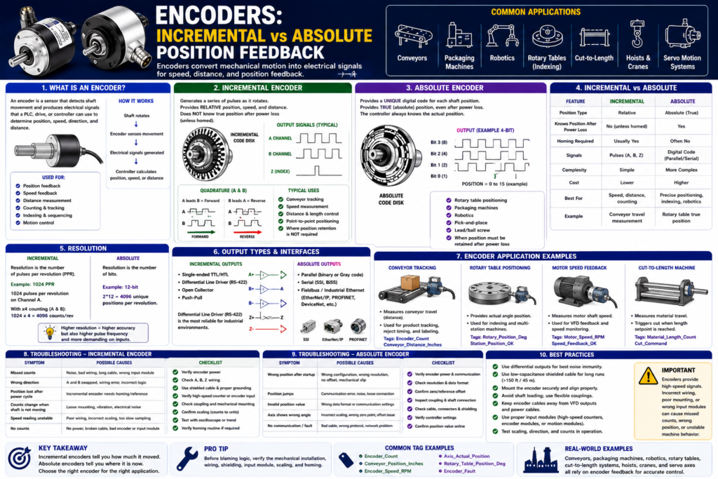
Pick-and-place machinesThe Rockwell Automation sensor manual explains that incremental encoders generate pulses as they move and provide relative position, speed, and distance feedback. Absolute encoders provide a unique digital output for each shaft position and can provide true position even after power loss.
In simple words:
Incremental encoder = counts movement from a reference point.
Absolute encoder = knows actual position.
What Is an Encoder?
An encoder is a sensor used to measure motion.
It is usually mounted to a rotating shaft, motor, conveyor roller, ball screw, lead screw, or machine axis.
Basic concept:
Shaft rotates
↓
Encoder detects movement
↓
Encoder sends pulses or position data
↓
Controller interprets speed, direction, distance, or position
PLC tag examples:
Encoder_Count
Encoder_Position
Encoder_Speed_RPM
Conveyor_Distance_Inches
Axis_Actual_Position
Axis_Actual_Speed
Unlike a limit switch or proximity sensor, an encoder can provide many signals over time instead of only one ON/OFF position.
Why Encoders Matter in PLC Systems
A normal proximity sensor may only tell the PLC:
Target present
or
Target not present
But an encoder can tell the PLC or controller:
The shaft moved 500 pulses.
The conveyor traveled 12 inches.
The motor is running at 1750 RPM.
The axis is at 42.35 degrees.
The machine moved forward or reverse.
This makes encoders useful when the machine needs more than simple position confirmation.
Example:
A conveyor moves product forward.
The encoder generates pulses as the conveyor moves.
The PLC counts pulses.
The PLC knows how far the product traveled.
This can be used for:
Product tracking
Reject timing
Cut-to-length control
Indexing
Speed monitoring
Jam detection
Position control
Two Main Encoder Types
There are two major encoder categories:
1. Incremental Encoders
2. Absolute Encoders
Both measure motion, but they provide feedback differently.
1. Incremental Encoders
What Is an Incremental Encoder?
An incremental encoder generates a series of pulses as it rotates.
The controller counts those pulses to determine movement.
The Rockwell manual explains that incremental encoders generate a series of pulses as they move and provide relative values. They are typically simple and inexpensive and provide relative position information.
Simple idea:
Encoder rotates
↓
Pulse, pulse, pulse, pulse
↓
PLC or counter counts pulses
↓
Position or speed is calculated
An incremental encoder does not automatically know the actual machine position after power is lost.
It only knows movement relative to where counting started.
Incremental Encoder Example
Imagine a conveyor with an encoder mounted to a roller.
Every time the roller turns, the encoder generates pulses.
Example:
1000 pulses = 1 revolution
1 revolution = 12 inches of conveyor travel
If the PLC counts 500 pulses:
Conveyor moved approximately 6 inchesThis is simplified, but it shows the concept.
Common Incremental Encoder Signals
Many incremental encoders use channels such as:
A
B
Z
Channel A
Channel A provides pulses as the encoder rotates.
Used for:
Counting movement
Measuring speed
Channel B
Channel B is another pulse train offset from Channel A.
Used for:
Direction detection
Forward/reverse movement
Quadrature counting
Channel Z
Channel Z is usually an index pulse.
It often occurs once per revolution.
Used for:
Home reference
Index reference
One pulse per revolution
Simple concept:
A and B = movement and direction
Z = reference pulse
What Is Quadrature?
Many incremental encoders use quadrature signals.
This means Channel A and Channel B are offset from each other.
The controller looks at which channel turns ON first to determine direction.
Example:
A leads B = forward
B leads A = reverse
This allows the PLC, counter, or motion controller to know:
How many pulses occurred
Which direction the shaft moved
How fast the shaft is moving
Important:
A standard PLC input may not be fast enough for encoder pulses.
Often you need a high-speed counter module, encoder input, drive input, or motion controller.
Incremental Encoder Advantages
Incremental encoders are very common because they are practical and cost-effective.
Advantages:
Simple design
Usually less expensive than absolute encoders
Good for speed feedback
Good for distance measurement
Good for counting pulses
Useful for conveyor tracking
Common in many machines
Can provide direction with A/B channels
The Rockwell manual notes that incremental encoders are used for velocity control, point-to-point applications, and sequencing.
Incremental Encoder Disadvantages
Incremental encoders also have limitations.
Disadvantages:
Position is relative, not absolute
Position may be lost on power loss
Usually requires homing or reference position
Requires counter or high-speed input
Can lose accuracy if pulses are missed
Wiring noise can cause false counts
Mechanical slip can cause position error
Important point:
If the machine loses power, an incremental encoder may need to be re-homed before accurate position is known.Example:
Machine power is turned off.
Operator manually moves the axis.
Power is restored.
The controller does not automatically know the new actual position.
Unless the system has battery backup, position retention, or a homing routine, the position reference may be lost.
2. Absolute Encoders
What Is an Absolute Encoder?
An absolute encoder provides a unique position value for each shaft position.
Instead of only sending pulses to count, it sends an actual position code.
The Rockwell manual explains that an absolute encoder has a unique digital output for each shaft position and provides true absolute position regardless of power interruptions. When power is restored, the encoder provides the correct absolute position.
Simple idea:
Encoder shaft position = unique digital code
Controller reads code
Controller knows actual position
An absolute encoder is like a position sensor that always knows where it is.
Absolute Encoder Example
Imagine a rotary table.
The table can stop at different positions:
0 degrees
90 degrees
180 degrees
270 degrees
With an absolute encoder, each position has a unique value.
If the machine loses power at 180 degrees and power comes back later, the controller can still read the encoder and know:
Rotary table position = 180 degreesThis is very useful for machines where position must be retained after shutdown or power loss.
Absolute Encoder Advantages
Advantages:
Provides true position
Position is retained after power loss
No homing required in many applications
Good for rotary position
Good for multi-position machines
Useful for robotics and servo applications
Reduces startup uncertainty
The Rockwell manual states that absolute encoders are used in packaging machines, robotics, lead/ball screw applications, rotary table positioning, pick-and-place, and component insertion applications.
Absolute Encoder Disadvantages
Disadvantages:
Usually more expensive
More complex wiring or communication
May require special input module or network
Resolution and format must match controller
Setup/configuration may be more involved
Replacement must match type and configuration
Absolute encoders are powerful, but they require more understanding of communication, resolution, scaling, and controller configuration.
Incremental vs Absolute Encoders
| Feature | Incremental Encoder | Absolute Encoder |
|---|---|---|
| Feedback type | Pulses | Unique position value |
| Position type | Relative | Absolute |
| Needs homing? | Usually yes | Often no |
| Power loss behavior | Position may be lost | Position retained |
| Common use | Speed, distance, counting | True position feedback |
| Cost | Usually lower | Usually higher |
| Complexity | Simpler | More complex |
| PLC input | High-speed counter/encoder input | Special module, network, or digital code |
| Example | Conveyor distance tracking | Rotary table position |
Simple takeaway:
Incremental = how much did it move?
Absolute = where is it now?
Encoder Resolution
Resolution tells you how many counts or positions the encoder provides per revolution.
For incremental encoders, resolution is often listed as:
PPR = Pulses Per RevolutionExample:
Encoder resolution = 1024 PPRThis means the encoder produces 1024 pulses per revolution on the main channel.
With quadrature counting, the controller may count more edges depending on configuration.
Example:
1024 PPR encoder
x4 quadrature counting
= 4096 counts per revolution
For absolute encoders, resolution may be listed as bits.
Example:
12-bit absolute encoder
2^12 = 4096 positions per revolution
Higher resolution means the controller can detect smaller changes in position.
But higher resolution also means:
More counts to process
Higher pulse frequency at speed
More need for proper input hardware
More sensitivity to wiring/noise issues
Encoder Speed Feedback
Encoders are commonly used to measure speed.
The controller can calculate speed by counting how many pulses occur over time.
Example:
More pulses per second = faster shaft speed
Fewer pulses per second = slower shaft speed
Applications:
Conveyor speed monitoring
Motor speed feedback
Line speed calculation
Roll speed
RPM display on HMI
Jam detection
Speed matching between conveyors
Example PLC tag:
Encoder_Speed_RPM
Conveyor_Speed_FPM
Encoder Position Feedback
Encoders are also used for position.
The controller can calculate position by counting pulses or reading absolute position.
Applications:
Indexing table
Cut-to-length machine
Servo axis
Lead screw
Ball screw
Robotic arm
Pick-and-place mechanism
Conveyor tracking
Example PLC tags:
Axis_Actual_Position
Conveyor_Position_Count
Rotary_Table_Position_Deg
Cut_Length_Inches
Incremental Encoder PLC Example
Application:
Measure conveyor travel distance.Encoder:
Incremental encoder mounted to conveyor rollerPLC/controller data:
Encoder_Count
Conveyor_Distance_Inches
Conveyor_Speed_FPM
Basic concept:
Encoder pulses counted by high-speed counter
↓
Counts converted to distance
↓
PLC tracks product position
Example logic concept:
If Conveyor_Distance_Inches >= Reject_Position
Then Fire_Reject_Output
This is common in reject systems where product must be tracked after an inspection sensor.
Absolute Encoder PLC Example
Application:
Rotary table positioning.Encoder:
Absolute encoder mounted to rotary table shaftController data:
Rotary_Table_Position_DegBasic concept:
Controller reads actual table angle
↓
Compares to target position
↓
Commands motion until position is reached
Example logic concept:
If Rotary_Table_Position_Deg = 90 degrees
Then Station_2_Position_Confirmed
If the machine loses power and returns, the absolute encoder can still report the actual table position.
Encoder Wiring and Signal Quality
Encoders can be sensitive to wiring issues because they often send high-speed signals.
Important wiring considerations:
Shielded cable
Proper grounding
Correct cable type
Differential signals when available
Avoid routing near VFD output cables
Avoid high-noise power wiring
Correct termination
Secure connectors
Correct input module
The Rockwell manual recommends differential line driver outputs for the most reliable incremental encoder signals. It also notes that low-capacitance cable is recommended for cable lengths greater than 150 feet to help prevent signal distortion.
Important field rule:
Encoder signals are not ordinary slow digital inputs.
Treat them like high-speed feedback signals.
Encoder Mechanical Installation
Encoder feedback accuracy depends on mechanical installation.
Check:
Shaft alignment
Coupling type
Mounting bracket rigidity
Bearing load
Vibration
Loose coupling
Slippage
Mechanical backlash
Cable strain relief
Protection from impact
Example problem:
Encoder count changes incorrectly.Possible cause:
Loose coupling slipping on the shaft.The PLC may count correctly, but the encoder is no longer mechanically tracking the shaft accurately.
That is a mechanical feedback problem, not necessarily a PLC logic problem.
Common Encoder Applications
1. Conveyor Tracking
Encoder measures conveyor movement.
PLC tracks product position.
Used for sorting, rejecting, labeling, or spacing.
Tags:
Encoder_Count
Conveyor_Position
Conveyor_Speed_FPM
2. Cut-to-Length
Encoder measures material travel.
PLC or controller triggers cut when length is reached.
Tags:
Material_Length_Count
Cut_Length_Setpoint
Cut_Command
3. Rotary Table Positioning
Encoder provides rotary angle feedback.
Controller confirms station position.
Tags:
Rotary_Position_Deg
Station_Position_Confirmed
4. Motor Speed Feedback
Encoder provides motor shaft speed.
Drive or controller uses speed feedback.
Tags:
Motor_Speed_RPM
Speed_Feedback_OK
5. Servo Axis Feedback
Encoder provides high-resolution position feedback.
Servo drive controls position, speed, and torque.
Tags:
Axis_Actual_Position
Axis_Actual_Velocity
Axis_Position_Error
Troubleshooting Incremental Encoders
Common symptoms:
Missed counts
Wrong direction
Position drift
Speed reading unstable
Machine needs homing repeatedly
Counter not changing
Counts changing when stopped
Possible causes:
Bad A/B wiring
A and B reversed
Noise on encoder cable
Wrong input module
Pulse rate too fast for input
Loose coupling
Wrong scaling
Missing Z pulse
Damaged encoder
Bad shield/grounding
Troubleshooting checklist:
1. Verify encoder power.
2. Check encoder output type.
3. Check A, B, and Z wiring.
4. Verify input module supports encoder frequency.
5. Check count direction.
6. Check shielded cable and grounding.
7. Inspect coupling and mechanical mounting.
8. Compare count movement to actual machine movement.
9. Verify scaling counts-to-distance.
10. Check if homing routine works correctly.
Troubleshooting Absolute Encoders
Common symptoms:
Wrong position after startup
Position jumps
Controller reads invalid value
Position offset incorrect
Axis shows wrong angle
Communication fault
Position does not match machine
Possible causes:
Wrong encoder configuration
Incorrect resolution setting
Wrong communication format
Bad cable or connector
Mechanical coupling slipped
Wrong zero/reference offset
Incorrect scaling
Wrong code format
Power or network issue
Troubleshooting checklist:
1. Verify encoder power and communication.
2. Check encoder type and resolution.
3. Verify controller configuration.
4. Confirm actual mechanical position.
5. Check zero/reference offset.
6. Inspect coupling and shaft connection.
7. Check cable and connector.
8. Verify position value changes smoothly.
9. Confirm position after power cycle.
10. Check machine documentation before replacing.
Encoder vs Proximity Sensor
| Feature | Encoder | Proximity Sensor |
|---|---|---|
| Feedback type | Pulses or position data | ON/OFF detection |
| Measures speed | Yes | Limited, with pulse detection |
| Measures position | Yes | Usually only one position |
| Detects target | Shaft/motion feedback | Metal/object presence |
| Requires high-speed input | Often yes | Usually no |
| Used for motion | Yes | Basic position confirmation |
| Example | Conveyor distance tracking | Cylinder extended feedback |
Simple takeaway:
A proximity sensor proves one point.
An encoder tracks motion over many points.
Encoder vs Limit Switch
| Feature | Encoder | Limit Switch |
|---|---|---|
| Contact | Usually non-contact internal sensing | Physical contact actuator |
| Feedback | Continuous motion/position | One mechanical position |
| Wear | Low, but mechanical mounting matters | Actuator/contact wear possible |
| Best for | Speed, distance, position tracking | End-of-travel confirmation |
| Power loss | Depends on incremental vs absolute | State depends on physical position |
| Example | Conveyor travel measurement | Door fully closed feedback |
Simple takeaway:
Limit switch = position proof at one point.
Encoder = motion/position feedback over a range.
PLC Logic Considerations
Encoders are not usually handled like normal push buttons or limit switches.
For incremental encoders, the PLC often needs:
High-speed counter
Encoder module
Motion module
Drive feedback input
Fast task
Proper scaling
Homing routine
For absolute encoders, the PLC may need:
Digital input word
SSI module
EtherNet/IP device
IO-Link master
Motion controller
Drive communication
Scaling and offset setup
Important:
Do not connect high-speed encoder channels to normal inputs unless the input module and application support it.A normal digital input module may miss pulses if the encoder is moving fast.
Good PLC Tag Names
Good tag examples:
Encoder_Count
Encoder_Position_Counts
Encoder_Speed_RPM
Conveyor_Speed_FPM
Conveyor_Position_Inches
Axis_Actual_Position
Axis_Actual_Velocity
Rotary_Table_Position_Deg
Encoder_Home_Z_Pulse
Encoder_Fault
Encoder_Signal_OK
Avoid unclear names:
Encoder1
Pulse
CountA
Input_7
PositionThing
A good tag name should describe what the value means.
Recommended Documentation Format
Example for incremental encoder:
Tag Name:
Conveyor_Encoder_Count

Device Type:
Incremental encoder

Application:
Conveyor travel tracking

Signals:
Channel A, Channel B, optional Z index

Controller Interface:
High-speed counter module

Resolution:
1024 PPR

PLC Use:
Product tracking, conveyor speed, reject timing

Important Notes:
Requires proper shielding, grounding, scaling, and homing/reference logic if absolute position is needed.

Troubleshooting:
Check power, A/B signals, count direction, input module frequency, cable shield, coupling, and counts-to-distance scaling.
Example for absolute encoder:
Tag Name:
Rotary_Table_Position_Deg

Device Type:
Absolute encoder

Application:
Rotary table position feedback

Signal Type:
Absolute position data

PLC Use:
Station position confirmation, motion control, HMI position display

Important Notes:
Position is retained after power loss. Verify resolution, scaling, zero offset, and communication settings.

Troubleshooting:
Check encoder power, communication, position value, mechanical coupling, offset, and controller configuration.
Technician Mindset
When working with encoders, do not only ask:
Is the encoder ON?Ask:
Is it incremental or absolute?
Does the controller need speed, distance, or true position?
Is position required after power loss?
Is a homing routine required?
What is the resolution?
Can the input module handle the pulse frequency?
Is the wiring shielded and grounded correctly?
Is the mechanical coupling secure?
Is the scaling correct?
Does the direction match the machine movement?
This mindset helps you troubleshoot encoder issues much faster.
Final Thoughts
Encoders are powerful feedback devices used when a PLC, drive, or motion controller needs more information than a simple ON/OFF signal.
An incremental encoder generates pulses as it moves. It is excellent for speed, distance, counting, and relative position feedback. However, it usually requires a reference or homing routine if true position is needed after power loss.
An absolute encoder provides a unique position value for each shaft position. It is used when the controller must know the actual position, even after power is removed and restored.
The key takeaway is:
Incremental encoders count movement.
Absolute encoders report actual position.
For PLC technicians, the most important rule is:
Encoder feedback depends on both electrical signal quality and mechanical installation.Good encoder feedback requires the correct sensor type, correct input hardware, correct wiring, proper shielding, accurate scaling, and solid mechanical coupling.
When applied correctly, encoders allow industrial machines to track position, measure speed, control motion, improve accuracy, and troubleshoot movement problems more effectively.