13. Sensor Troubleshooting: When the PLC Does Not See the Input (13 of 15)
Introduction
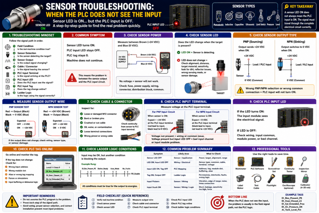
One of the most common troubleshooting situations in industrial automation is when a field sensor appears to be working, but the PLC does not see the input.
A technician may see the sensor LED turn ON when the target is present, but the PLC input LED does not turn ON, the PLC tag stays OFF, and the machine sequence does not continue.
This can happen with many types of sensors:
Photoelectric sensors
Inductive proximity sensors
Capacitive sensors
Ultrasonic sensors
Limit switches
Pressure switches
Level switches
Motor feedback contacts
Safety-related feedback devices
The important point is this:
A sensor LED ON does not always mean the PLC input is ON.The sensor may be detecting the target, but the signal may not be reaching the PLC input module correctly.
The Rockwell Automation sensor reference manual explains that the connection between the sensor, power supply, and load device is the electrical interface circuit, and each part of that circuit is important for reliable operation. It also explains that improper installation, direct connection mistakes, wrong ratings, reverse polarity, short circuits, and load issues can cause sensor problems.
In simple words:
The PLC input only turns ON when the complete electrical circuit is correct.The Basic Troubleshooting Mindset
When the PLC does not see a sensor input, do not start by changing the ladder logic.
Start with the field signal.
A professional troubleshooting path is:
Field condition
↓
Sensor detection
↓
Sensor output
↓
Cable and connector
↓
PLC input terminal
↓
PLC input LED
↓
PLC input tag
↓
Ladder logic
This order helps prevent guessing.
Many input problems are not PLC programming problems. They are usually caused by:
No sensor power
Wrong sensor type
Wrong output type
Wrong input common
Broken cable
Loose connector
Bad input channel
Wrong tag mapping
Dirty sensor
Misalignment
Target problem
Incorrect sensor mode
Wrong wiring
Common Symptom
The most common symptom looks like this:
Sensor LED turns ON.
PLC input LED stays OFF.
PLC tag stays 0.
Machine does not continue.
This tells us something important:
The sensor may be detecting the target,
but the PLC is not receiving a valid input signal.
That means the problem is likely between the sensor output and the PLC input circuit.
Step 1: Confirm the Real Machine Condition
Before checking wires, verify the actual field condition.
Ask:
Is the target actually present?
Is the door actually closed?
Is the cylinder actually extended?
Is the product actually in position?
Is the pressure actually OK?
Is the tank level actually high or low?
Example:
PLC tag: DI_Door_Closed_LS
Expected condition: Door fully closed
Do not only trust the HMI. Look at the real machine.
If the real condition is not true, the sensor should not be expected to turn ON.
Step 2: Check Sensor Power
Most modern industrial sensors require power.
For a typical 3-wire DC sensor:
Brown = +24 VDC
Blue = 0 VDC / Common
Black = Output signal
Check with a multimeter:
Measure between brown and blue.
Expected reading: approximately 24 VDC
If there is no voltage:
Sensor will not work.
Sensor LED may stay OFF.
PLC input will not turn ON.
Possible causes:
Blown fuse
Bad power supply
Broken wire
Loose M12 connector
Wrong terminal
Bad distribution block
Missing common
Damaged cable
Important:
Always verify power at the sensor, not only inside the panel.A sensor may have 24 VDC available in the cabinet, but not at the field device due to a cable or connector problem.
Step 3: Check the Sensor LED
Most sensors have an LED that indicates detection or output status.
If the LED does not change:
The sensor may not be detecting the target.Possible causes:
Sensor not powered
Target too far away
Wrong target material
Dirty lens
Misalignment
Bad reflector
Sensor sensitivity incorrect
Wrong sensing mode
Sensor damaged
Target inside blind zone
Wrong sensor type for application
Example:
An inductive proximity sensor will not detect a plastic target.
A photoelectric sensor may struggle with a clear or shiny target.
A capacitive sensor may need sensitivity adjustment.
An ultrasonic sensor may not detect if the target angle reflects the echo away.
Step 4: Check the Sensor Output Type
This is one of the biggest causes of PLC input problems.
The sensor may be:
PNP
NPN
2-wire
3-wire
Relay output
AC sensor
DC sensor
Analog output
IO-Link sensor
The PLC input module must be compatible with the sensor output.
For a 3-wire DC sensor:
PNP = sourcing output
NPN = sinking output
Simple memory rule:
PNP switches +24 VDC.
NPN switches 0 VDC/common.
If a PNP sensor is installed where an NPN sensor is required, the sensor LED may work, but the PLC input may not turn ON.
Same thing if an NPN sensor is installed where the input wiring expects PNP.
Step 5: Check the PLC Input Common
The PLC input common is critical.
A PLC input turns ON only when current has a complete path.
For many PNP sensor applications:
Sensor output sends +24 VDC to PLC input.
PLC input common must be connected to 0 VDC.
For many NPN sensor applications:
PLC input common is connected to +24 VDC.
Sensor output provides path to 0 VDC.
If the common is wrong or missing:
Sensor output may change,
but PLC input will not energize.
This is a very common field issue.
Example:
PNP sensor output = +24 VDC when ON
PLC input common = not connected to 0 VDC
Result = PLC input stays OFF
The circuit is incomplete.
Step 6: Measure the Sensor Output Wire
For a typical 3-wire DC sensor:
Black wire = output signalTesting a PNP Sensor
Meter setup:
Red lead → black output wire
Black lead → blue/common
Expected result:
Sensor OFF ≈ 0 VDC
Sensor ON ≈ +24 VDC
If the sensor LED turns ON but the black wire does not output +24 VDC:
Wrong sensor type
Damaged output
Incorrect wiring
Sensor not actually switching output
Testing an NPN Sensor
NPN can be more confusing with a meter because the output pulls toward common.
One method:
Red lead → brown/+24 VDC
Black lead → black output wire
When the NPN sensor is ON, the black wire is pulled toward 0 VDC, so the meter may show approximately 24 VDC across that path.
Another method:
Measure black output to blue/common.Expected:
Sensor ON = black output near 0 VDCImportant:
Always verify the sensor wiring diagram because NPN testing can be confusing without a proper load or input circuit.Step 7: Check the Cable and Connector
Sensor cables fail often in industrial environments.
Check:
M12 connector tightness
Bent pins
Water inside connector
Damaged cable jacket
Crushed cable
Broken conductor
Oil or chemical damage
Loose terminal
Wrong pinout
Cable swapped with another sensor
A sensor may have power but the output wire may be broken.
Example:
Brown and blue are good.
Sensor LED works.
Black output wire is open.
PLC never sees the signal.
This is why it is important to measure the signal at both places:
At the sensor output
At the PLC input terminal
If the signal exists at the sensor but not at the PLC, the problem is between the sensor and the input module.
Step 8: Check the PLC Input Terminal
Measure voltage at the PLC input terminal.
For a PNP input circuit:
When sensor is ON:
PLC input terminal should receive approximately +24 VDC.
If +24 VDC is present at the PLC input terminal but the input LED is OFF:
Possible causes:
Input common missing
Input module not powered
Bad input channel
Wrong voltage range
Input module fault
Wrong terminal
If +24 VDC is not present at the PLC input terminal but it is present at the sensor output:
Possible causes:
Broken wire
Bad connector
Bad junction box
Wrong cable
Loose terminal
Incorrect wiring
Step 9: Check the PLC Input LED
The input LED is a useful diagnostic point.
If the PLC input LED turns ON:
The input module is seeing the electrical signal.If the input LED is ON but the PLC tag is OFF:
Possible causes:
Wrong input address
Wrong tag mapping
Wrong controller chassis/module slot
Input not mapped correctly
Program looking at different tag
Forces or simulation logic active
Module fault or communication issue
This is where the troubleshooting moves from electrical to PLC configuration/programming.
Step 10: Check the PLC Tag Online
Go online with the PLC and verify the actual input tag.
Example tag:
DI_Box_Present_PECheck:
Does the tag change when the sensor changes?
Is the tag mapped to the correct physical input?
Is the program using the correct tag?
Is the tag inverted somewhere?
Is there input buffering?
Is there debounce logic?
Is there an alias tag?
Example problem:
PLC input LED turns ON.
But DI_Box_Present_PE stays OFF.
Possible cause:
The input is wired to Local:1:I.Data.3,
but the tag is mapped to Local:1:I.Data.4.
That is not a sensor problem. That is an addressing or mapping problem.
Step 11: Check Input Buffering Logic
Many professional PLC programs use input buffering.
Example:
Physical Input → Buffered Input Tag → Debounced Tag → Machine LogicExample:
Local:1:I.Data.0 → DI_Box_Present_PE → Box_Present_StableThis is good practice, but it means the physical input may be ON while the final logic tag is still OFF because of debounce, validation, fault logic, or a permissive condition.
Check:
Raw input
Buffered input
Debounced input
Final logic bit
Example:
Raw input is ON.
DI_Box_Present_PE is ON.
Box_Present_Stable is OFF.
Possible reason:
Debounce timer has not completed.
Signal is flickering.
Validation condition is missing.
Step 12: Check the Ladder Logic Condition
Once the field signal and PLC input tag are proven, then check the ladder logic.
Possible issues:
Logic uses XIC when it should use XIO
Wrong tag used
Input is being sealed around incorrectly
Fault condition blocks the command
Permissive is missing
Interlock is active
State machine is not in the correct state
Timer is not resetting
Latch is holding previous state
Example:
DI_Door_Closed_LS = ON
But Machine_Run_Command is still OFF.
That may be correct if another condition is false:
Stop_OK = OFF
No_Faults = OFF
Auto_Mode = OFF
Guard_Closed = OFF
Drive_Ready = OFF
Do not assume the sensor is the only condition in the rung.
Common Problem 1: Sensor LED ON, PLC Input OFF
Possible Causes
Wrong sensor output type
PNP/NPN mismatch
Wrong PLC input common
Broken black output wire
Bad M12 connector
Wrong input terminal
Input module not powered
Bad input channel
Wrong voltage sensor
2-wire sensor compatibility issue
Troubleshooting Path
1. Confirm sensor power.
2. Confirm sensor LED changes.
3. Identify sensor output type.
4. Measure output wire.
5. Measure at PLC input terminal.
6. Check PLC input common.
7. Check PLC input LED.
8. Check PLC tag online.
Common Problem 2: PLC Input ON, But Tag OFF
Possible Causes
Wrong input address
Wrong alias tag
Wrong module slot
Wrong mapping
Input buffering issue
Program using a different tag
Communication issue
Forces or test logic active
Troubleshooting Path
1. Confirm physical input LED.
2. Open controller input data.
3. Verify exact bit address.
4. Compare electrical drawing to PLC tag.
5. Check alias or mapped tag.
6. Search cross references.
7. Confirm logic uses the correct tag.
Common Problem 3: Input Flickers
Possible Causes
Sensor at edge of sensing range
Target vibration
Loose sensor mount
Dirty photoeye lens
Reflector misalignment
Weak sensing margin
Electrical noise
Loose connector
Bad cable
Capacitive sensor detecting moisture or buildup
Ultrasonic sensor receiving unstable echo
Mechanical limit switch bouncing
Troubleshooting Path
1. Watch sensor LED.
2. Watch PLC input online.
3. Check target position.
4. Check mounting and alignment.
5. Clean sensor face or reflector.
6. Measure output voltage stability.
7. Check cable routing near noise sources.
8. Add debounce only after fixing physical issues.
Important:
Debounce can help, but it should not hide a bad sensor installation.Common Problem 4: Input Stays ON
Possible Causes
Sensor stuck ON
Target always present
Sensitivity too high
Photoeye seeing background reflection
Capacitive sensor detecting buildup or moisture
Limit switch actuator stuck
Wiring short
2-wire sensor leakage current
PLC input forced ON
Wrong normally open/normally closed logic
Troubleshooting Path
1. Remove target.
2. Check if sensor LED turns OFF.
3. Disconnect output wire if safe and approved.
4. Check PLC input status.
5. Inspect wiring for short.
6. Check force table.
7. Verify sensor mode and sensitivity.
Common Problem 5: Sensor Works, But Machine Still Does Not Run
This is where many technicians get trapped.
A sensor may be working correctly, but the machine still does not run because the input is only one condition.
Example:
DI_Box_Present_PE = ON
But Fill_Enable = OFF
Other possible missing conditions:
Auto_Mode
Station_Ready
No_Faults
Air_Pressure_OK
Guard_Closed
Drive_Ready
E_Stop_OK
Valve_Home
Previous_Step_Complete
PLC logic is usually based on many permissives.
Example:
DI_Box_Present_PE
AND Station_Ready
AND Auto_Mode
AND No_Faults
AND Air_Pressure_OK
= Fill_Enable
If one condition is false, the output stays OFF.
Field Troubleshooting Flow
Use this practical flow:
1. What input should be ON?
2. What physical device controls that input?
3. Is the real-world condition true?
4. Is the sensor powered?
5. Does the sensor LED change?
6. Does the sensor output wire change?
7. Does the signal reach the PLC terminal?
8. Does the PLC input LED turn ON?
9. Does the PLC tag change online?
10. Is the program using the correct tag?
11. Is the logic blocked by another permissive, interlock, alarm, or fault?
This prevents random guessing.
Example 1: Photoeye Detects Box, PLC Input OFF
Symptom
Box is present.
Photoeye LED turns ON.
PLC input LED stays OFF.
DI_Box_Present_PE stays OFF.
Possible Causes
PNP/NPN mismatch
Wrong input common
Broken output wire
Bad M12 cable
Wrong terminal
Photoeye output mode wrong
PLC input channel bad
Checks
Measure brown to blue = 24 VDC.
Trigger sensor.
Measure black output wire.
Measure voltage at PLC input terminal.
Check input common.
Check PLC input LED.
Check tag online.
Likely Fix
Correct wiring, replace damaged cable, install correct PNP/NPN sensor, or correct input common.Example 2: Proximity Sensor Flickers on Cylinder
Symptom
Cylinder extended prox turns ON and OFF rapidly.
Sequence sometimes advances.
Sometimes cylinder timeout fault occurs.
Possible Causes
Metal target too far from sensor
Cylinder vibration
Loose sensor bracket
Wrong target material
Sensor at edge of range
Unshielded sensor affected by nearby metal
Bad cable
Checks
Watch sensor LED while cylinder is extended.
Move target closer if possible.
Check mounting tightness.
Verify target material.
Check sensor distance.
Check PLC input online.
Likely Fix
Adjust sensor position, secure bracket, improve target, or replace sensor with correct sensing range/type.Example 3: Limit Switch Shows Door Closed Sometimes
Symptom
Door appears closed.
PLC sometimes does not see DI_Door_Closed_LS.
Door close timeout fault occurs.
Possible Causes
Limit switch not fully actuated
Door misalignment
Weak actuator travel
Damaged roller
Ice or debris
Loose switch mount
Bad contact
Broken wire
Checks
Manually actuate switch.
Check PLC input LED.
Inspect actuator travel.
Check overtravel.
Check mechanical alignment.
Check wiring continuity.
Likely Fix
Adjust switch, repair actuator, clean obstruction, fix door alignment, or replace switch.Example 4: Analog Sensor Value Does Not Change
Although this post focuses on digital inputs, analog sensor troubleshooting is also important.
Symptom
Tank level changes.
HMI level stays at 0%.
Possible Causes
Transmitter not powered
Open 4–20 mA loop
Analog card configured wrong
Wrong channel
Bad scaling
Broken cable
Wrong input type current/voltage
Sensor failed
Checks
Check transmitter power.
Measure loop current.
Check analog module configuration.
Verify raw value.
Check scaling logic.
Compare HMI value to PLC value.
Important:
For analog sensors, do not only ask if the input is ON.
Ask if the value makes sense.
Digital Input Troubleshooting Table
| Symptom | Likely Area | What to Check |
|---|---|---|
| Sensor LED OFF | Sensor/application | Power, target, alignment, range |
| Sensor LED ON, input LED OFF | Wiring/electrical | Output type, common, cable, terminal |
| Input LED ON, tag OFF | PLC mapping | Address, alias, module slot, tag |
| Tag ON, logic output OFF | Ladder logic | Permissives, interlocks, faults |
| Input flickers | Sensor/application | Vibration, range, noise, debounce |
| Input stuck ON | Sensor/wiring/logic | Target, short, leakage, force |
| Works sometimes | Intermittent issue | Connector, cable, mounting, environment |
PNP/NPN Quick Check
| Sensor Type | Output When ON | PLC Input Common Usually |
|---|---|---|
| PNP | Sends +24 VDC | 0 VDC |
| NPN | Switches to 0 VDC | +24 VDC |
Quick rule:
PNP = Positive output
NPN = Negative output
Field reminder:
If the sensor LED is ON but the PLC input is OFF, check PNP/NPN and common first.2-Wire Sensor Warning
2-wire sensors can be tricky.
They are wired in series with the input/load and may have:
Leakage current
Voltage drop
Minimum load requirements
Compatibility issues with PLC inputs
Possible symptom:
PLC input stays ON even when sensor should be OFF.Possible cause:
Leakage current through 2-wire sensor is enough to keep the PLC input active.Another symptom:
Sensor turns ON but PLC input does not turn ON fully.Possible cause:
Voltage drop across the sensor leaves insufficient voltage for the PLC input.Always check the datasheet and input module specifications.
Recommended Technician Tools
Useful tools for sensor troubleshooting:
Digital multimeter
Electrical drawings
PLC online software
Small screwdriver
Sensor datasheet
Known-good sensor or test cable
Continuity tester
Clamp meter for some circuits
Flashlight
Inspection mirror
Contact cleaner where allowed
Label maker
For advanced troubleshooting:
Oscilloscope for fast pulses
Loop calibrator for 4–20 mA signals
High-speed counter diagnostics
Network diagnostics for IO-Link or smart sensors
Good PLC Tag Names for Troubleshooting
Good tag names make troubleshooting much faster.
Good examples:
DI_Box_Present_PE
DI_Door_Closed_LS
DI_Cylinder_Extended_Prox
DI_Label_Detected_PE
DI_Air_Pressure_OK
DI_Motor_Run_FB
AI_Tank_Level_Pct
Poor examples:
Input_1
Sensor_A
PE3
Switch2
Bit_14
A good tag name should tell you:
What device it is
What condition it proves
What the signal means when ON
Recommended Documentation Format
Example:
Tag Name:
DI_Box_Present_PE

Device:
Photoelectric sensor

Signal Type:
24 VDC digital input

Output Type:
PNP sourcing

Normal State:
ON when box is present

PLC Input:
Local:1:I.Data.3

PLC Use:
Fill cycle permissive, product tracking, jam detection

Troubleshooting:
Check sensor power, LED, alignment, reflector, black output wire, PLC input terminal, input LED, and tag online.
Another example:
Tag Name:
DI_Cylinder_Extended_Prox

Device:
Inductive proximity sensor

Signal Type:
24 VDC digital input

Normal State:
ON when cylinder is fully extended

PLC Use:
Sequence step complete and extend timeout fault reset

Troubleshooting:
Check metal target, sensing distance, sensor LED, cable, PLC input LED, and tag online.
Technician Mindset
When the PLC does not see an input, do not immediately ask:
What is wrong with the PLC program?Ask:
What physical condition should make this input turn ON?
Is that condition actually true?
Is the sensor powered?
Is the sensor detecting?
Is the output wire changing?
Is the signal reaching the PLC input terminal?
Is the input common correct?
Is the PLC input LED ON?
Is the PLC tag mapped correctly?
Is the ladder logic using the correct tag?
This mindset separates field problems from logic problems.
Final Thoughts
When the PLC does not see a sensor input, the problem can be in many places:
The real machine condition
The sensor
The sensor power
The output type
The wiring
The connector
The PLC input common
The input module
The tag mapping
The input buffer
The ladder logic
A good technician troubleshoots in order.
The key takeaway is:
Start at the field device and work back to the PLC.And always remember:
Sensor LED ON does not guarantee PLC input ON.
PLC input LED ON does not guarantee the correct tag is being used.
Tag ON does not guarantee the output will energize.
Reliable troubleshooting means proving each step:
Sensor detects
Output switches
PLC input receives
Tag changes
Logic uses the signal correctly
That is how a PLC technician finds the real problem faster and avoids unnecessary parts replacement, downtime, and confusion.