11. Limit Switches: Mechanical Position Feedback in Industrial Machines (11 of 15)
Introduction
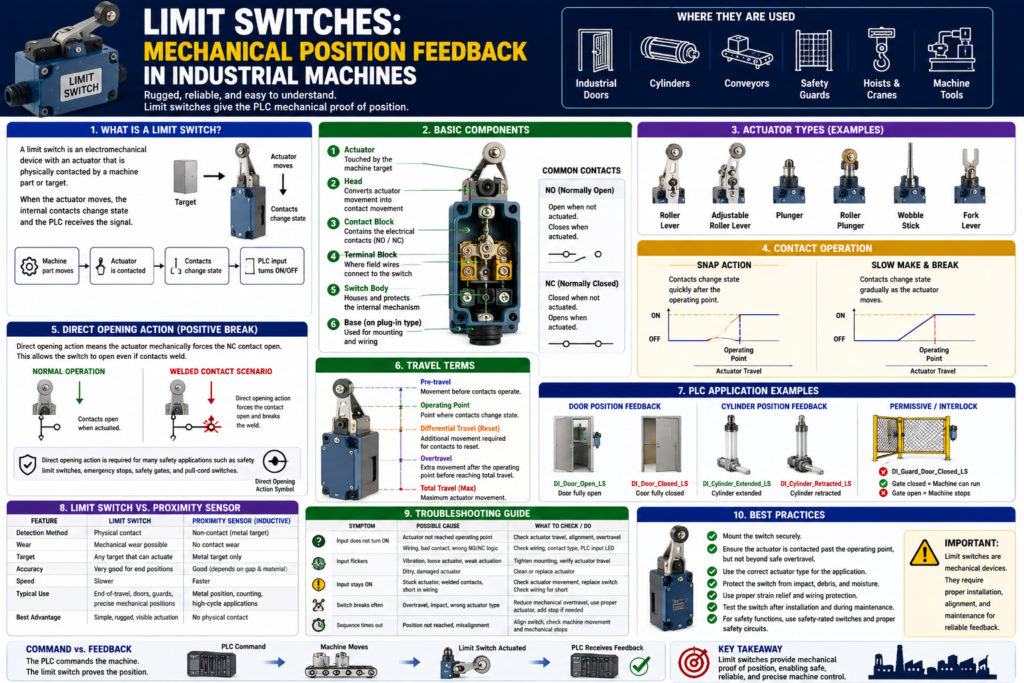
A limit switch is one of the most common and important feedback devices used in industrial machines.
Unlike photoelectric, inductive, capacitive, or ultrasonic sensors, a limit switch normally requires physical contact with the machine part or target.
In PLC systems, limit switches are commonly used to confirm:
Door fully open
Door fully closed
Cylinder extended
Cylinder retracted
Machine home position
End of travel
Guard closed
Part position
Conveyor stop position
The Rockwell Automation sensor manual defines a limit switch as an electromechanical device with an actuator mechanically linked to a set of contacts. When an object contacts the actuator, the switch operates the contacts to make or break an electrical connection.
In simple words:
A limit switch gives the PLC mechanical proof that something reached a position.What Is a Limit Switch?
A limit switch is a mechanical input device.
It has an actuator that moves when a machine part touches it.
That actuator operates internal electrical contacts.
Basic concept:
Machine part moves
↓
Machine part contacts limit switch actuator
↓
Actuator moves
↓
Internal contacts change state
↓
PLC input turns ON or OFF
Example:
Door reaches fully closed position
↓
Door hits limit switch roller
↓
Limit switch contact changes state
↓
PLC input confirms Door Closed
PLC tag example:
DI_Door_Closed_LSThe tag tells the PLC:
The door is physically in the closed position.Why Limit Switches Matter in PLC Systems
A PLC can command a device to move, but it needs feedback to confirm that the movement actually happened.
Example:
PLC Command:
Open Door

Expected Feedback:
Door Open Limit Switch turns ON
Without the limit switch, the PLC may only know that it energized the open output. It would not know if the door actually opened.
This is the difference between command and feedback.
Command = What the PLC asks the machine to do
Feedback = What the machine proves back to the PLC
Example:
Motor_Open_Command = ON
DI_Door_Open_LS = OFF
This means:
The PLC is commanding the door to open,
but the door has not proven fully open yet.
If the feedback does not arrive within the expected time, the PLC can generate a fault.
Door_Open_Command
AND NOT DI_Door_Open_LS
AND Open_Timer.DN
= Door_Open_Timeout_Fault
This is professional PLC logic.
Common Limit Switch Applications
Limit switches are used in many industrial applications because they are rugged, easy to install, and reliable. The Rockwell manual states that they can determine presence or absence, passing, positioning, and end-of-travel conditions.
Common applications include:
Conveyor systems
Transfer machines
Packaging machines
Machine tools
Industrial doors
Guard doors
Elevators
Hoists
Cranes
Scissor lifts
Material handling equipment
In PLC programs, they are often used as:
Position feedback
Travel limit feedback
Machine-ready permissives
Interlocks
Fault confirmation
HMI status indicators
Sequence step confirmations
Basic Limit Switch Components
A typical industrial limit switch has several main parts.
The Rockwell manual identifies key components such as the actuator, head, contact block, terminal block, switch body, and base. The actuator is the portion of the switch that contacts the object being sensed, and the head translates actuator movement into contact movement.
Main Components
| Component | Function |
|---|---|
| Actuator | The part touched by the machine target |
| Head | Converts actuator movement into contact movement |
| Contact block | Contains the electrical contacts |
| Terminal block | Where field wires connect |
| Switch body | Houses the internal mechanism |
| Base | Used on plug-in styles for wiring/mounting |
Simple concept:
Actuator movement → Contact movement → PLC input signalCommon Actuator Types
Limit switches can have different actuator styles depending on the application.
Common actuator types:
Roller lever
Adjustable roller lever
Plunger
Roller plunger
Wobble stick
Fork lever
Rotary shaft
Hinge lever
Dome plunger
Roller Lever
Very common for moving machine parts.
Example:
Door closes and rolls over the lever.
The lever moves.
The switch changes state.
Best for:
Doors
Slides
Conveyor stops
Moving arms
End-of-travel feedback
Plunger
A plunger is pushed directly by the target.
Best for:
Precise position detection
Short travel applications
Direct mechanical contact
Wobble Stick
A flexible actuator that can be contacted from different directions.
Best for:
Part passing detection
Material movement
Less precise but flexible contact
Normally Open and Normally Closed Contacts
Limit switches can have NO and NC contacts.
NO = Normally Open
NC = Normally Closed
Normally Open Contact
A normally open contact is open when the switch is not actuated.
When the actuator is pressed, the contact closes.
Not actuated = circuit open
Actuated = circuit closed
Normally Closed Contact
A normally closed contact is closed when the switch is not actuated.
When the actuator is pressed, the contact opens.
Not actuated = circuit closed
Actuated = circuit open
For many feedback applications, either can be used depending on the design.
For safety-related applications, contact selection and circuit design must follow the required safety standards and safety-rated hardware.
Snap Action vs Slow Make/Break
Limit switch contacts may operate in different ways.
Two common styles are:
Snap action
Slow make and break
Snap Action
A snap action switch changes contact state quickly once the operating point is reached.
Benefit:
Fast and decisive contact changeUseful for:
General position feedback
Repeatable switching
Applications where quick contact transfer is desired
Slow Make and Break
A slow make/break switch changes contact state more directly with actuator movement.
Benefit:
Contact movement follows actuator movement more directlyUseful for:
Certain safety-rated or controlled contact applicationsThe exact selection depends on the application and manufacturer specifications.
Direct Opening Action
Some limit switches are designed with direct opening action, also called positive opening action.
This is very important for safety-related applications.
The Rockwell manual explains that IEC 60947-5-1 defines positive break as contact separation resulting directly from specified movement of the actuator through non-resilient members, not dependent on springs. It also explains that direct opening action couples actuator force to the contacts so the force can break open even a welded contact.
In simple words:
Direct opening action means the actuator mechanically forces the NC contact open.This matters because if a contact welds, a normal spring-return mechanism may not be enough to open it.
Important applications:
Safety limit switches
Safety gate interlocks
Emergency stop switches
Cable pull safety switches
Disconnect switches
Important note:
If a limit switch is part of a safety function, use the correct safety-rated device and safety circuit.
Do not rely only on standard PLC logic for personnel safety.
Operating Travel Terms
Limit switches have mechanical movement specifications.
The Rockwell manual explains terms such as pre-travel, differential travel, total travel, and overtravel. Pre-travel is the movement before contacts operate, differential travel is the travel needed to reset contacts, and total travel or overtravel defines the maximum actuator movement range.
Important Terms
| Term | Meaning |
|---|---|
| Pre-travel | Movement before contact changes state |
| Operating point | Point where contact changes state |
| Differential travel | Movement needed before contact resets |
| Overtravel | Extra movement after the trip point |
| Total travel | Maximum actuator movement |
Why this matters:
The machine must move the actuator far enough to operate the contacts,
but not so far that it damages the switch.
Bad installation:
Door barely touches the limit switch.
Input flickers or does not turn ON reliably.
Another bad installation:
Door overdrives the limit switch.
Actuator bends or switch breaks.
Better installation:
Door actuates the switch past the operating point,
with safe overtravel,
without mechanical damage.
Limit Switches as Position Feedback
One of the most common uses of limit switches is mechanical position feedback.
Example:
DI_Door_Open_LS
DI_Door_Closed_LS
These inputs tell the PLC the actual door position.
Door Example
Door is closed:
DI_Door_Closed_LS = 1
DI_Door_Open_LS = 0
Door is open:
DI_Door_Closed_LS = 0
DI_Door_Open_LS = 1
Door is between positions:
DI_Door_Closed_LS = 0
DI_Door_Open_LS = 0
This is very useful in state-machine logic.
Example states:
Door_State = CLOSED
Door_State = OPENING
Door_State = OPEN
Door_State = CLOSING
Door_State = HALTED
Door_State = FAULTED
The limit switches help the PLC decide which state is true.
Using Limit Switches in PLC Logic
1. As a Permissive
A permissive allows an action only when a condition is true.
Example:
Machine can run only if guard door is closed.Logic concept:
Start_Request
AND DI_Guard_Door_Closed_LS
AND No_Faults
= Machine_Run_Command
Here, the limit switch confirms that the guard door is closed before the machine runs.
2. As an Interlock
An interlock prevents or stops an action when a condition changes.
Example:
Stop the machine if the door opens during operation.Logic concept:
Machine_Running
AND NOT DI_Guard_Door_Closed_LS
= Stop_Machine_Command
Important:
For personnel safety, use safety-rated devices and circuits.
Standard PLC interlocks are not a replacement for a safety system.
3. As End-of-Travel Feedback
A limit switch can stop motion when a mechanism reaches the end of travel.
Example:
Door opening command stops when open limit switch turns ON.Logic concept:
Open_Command
AND DI_Door_Open_LS
= Stop_Open_Output
Or in output logic:
Open_Output allowed only if NOT DI_Door_Open_LSThis prevents the motor from continuing to drive after the door reaches its open position.
4. As Fault Detection
A limit switch can help detect when a commanded movement failed.
Example:
PLC commands door to close.
Closed limit switch does not turn ON within 10 seconds.
Fault is latched.
Logic concept:
Door_Close_Command
AND NOT DI_Door_Closed_LS
TON Close_Timeout_Timer

Close_Timeout_Timer.DN
OTL Door_Close_Timeout_Fault
This tells maintenance:
The PLC commanded close,
but the door did not prove closed in time.
Practical Example: Industrial Door
Possible door feedback inputs:
DI_Door_Open_LS
DI_Door_Closed_LS
DI_Photo_Eye_Clear
DI_Motor_Run_FB
DI_Overload_OK
The limit switches are used to confirm the door end positions.
Open Sequence Example
Open_Request
AND NOT DI_Door_Open_LS
AND DI_Stop_OK
AND No_Faults
= Door_Open_Command
When the open limit switch turns ON:
DI_Door_Open_LS = 1The PLC can:
Stop Open Command
Set Door_State = OPEN
Start Auto_Close_Timer
Update HMI status
Reset Open Timeout Timer
Close Sequence Example
Close_Request
AND NOT DI_Door_Closed_LS
AND DI_Photo_Eye_Clear
AND DI_Stop_OK
AND No_Faults
= Door_Close_Command
When the closed limit switch turns ON:
DI_Door_Closed_LS = 1The PLC can:
Stop Close Command
Set Door_State = CLOSED
Reset Auto_Close_Request
Update HMI status
Reset Close Timeout Timer
Practical Example: Cylinder Position
A cylinder may use limit switches or proximity switches to confirm positions.
Tags:
DI_Cylinder_Extended_LS
DI_Cylinder_Retracted_LS
PLC use:
Sequence step complete
Fault if position not reached
HMI position status
Interlock next movement
Logic example:
Cylinder_Extend_Command
AND DI_Cylinder_Extended_LS
= Step_Extend_Complete
Fault example:
Cylinder_Extend_Command
AND NOT DI_Cylinder_Extended_LS
AND Extend_Timer.DN
= Cylinder_Extend_Timeout_Fault
Advantages of Limit Switches
Limit switches are still very useful in modern automation.
Advantages:
Simple to understand
Easy to troubleshoot
Rugged industrial construction
Good for mechanical position feedback
Can switch AC or DC depending on contact ratings
Visible actuator movement
Works well for end-of-travel detection
Many actuator styles available
No target material limitation like inductive sensors
The manual notes that limit switches are used across many environments because of ruggedness, ease of installation, and reliable operation.
Disadvantages of Limit Switches
Limit switches also have limitations.
Disadvantages:
Requires physical contact
Mechanical wear over time
Actuator can be damaged
Can be misaligned
Slower than many non-contact sensors
May require periodic adjustment
Can be affected by debris, ice, product buildup, or mechanical obstruction
Contact wear or oxidation can occur
Common field issue:
The machine reaches position,
but the switch actuator is not fully made.
The PLC never sees the input.
The sequence times out.
This is not necessarily a PLC problem. It is a feedback application problem.
Limit Switch vs Proximity Sensor
| Feature | Limit Switch | Inductive Proximity Sensor |
|---|---|---|
| Detection method | Physical contact | Non-contact metal detection |
| Wear | Mechanical wear possible | No contact wear |
| Target type | Any target that can actuate switch | Metal target only |
| Troubleshooting | Often easy visually | Requires sensing distance check |
| Best use | End-of-travel, rugged mechanical feedback | Metal position feedback without contact |
| Common failure | Broken actuator/misalignment | Target too far/material issue |
Simple takeaway:
Use a limit switch when physical position contact is acceptable.
Use a proximity sensor when non-contact metal detection is preferred.
Troubleshooting Limit Switches
Basic Checklist
When troubleshooting a limit switch, ask:
1. Is the actuator being contacted?
2. Is the actuator moving far enough?
3. Is there proper overtravel?
4. Is the switch mechanically damaged?
5. Is the lever bent or loose?
6. Is the roller stuck?
7. Is there dirt, ice, product, or debris blocking movement?
8. Are the contacts NO or NC?
9. Is the wiring correct?
10. Does the PLC input LED change?
11. Does the PLC tag change online?
12. Is the ladder logic using the correct input condition?
Common Symptoms and Causes
| Symptom | Possible Cause |
|---|---|
| PLC input does not turn ON | Switch not actuated, bad wiring, bad contact |
| Input flickers | Poor mechanical contact, vibration, weak actuation |
| Door closed but input OFF | Misalignment, not enough travel, broken actuator |
| Input stays ON | Stuck actuator, welded contact, wiring short |
| Switch breaks repeatedly | Overtravel, impact, bad mounting |
| Sequence times out | Position feedback not made in time |
| Machine stops randomly | Loose switch, vibration, intermittent contact |
| HMI status wrong | Wrong tag, wrong NO/NC logic, failed input |
Good PLC Tag Names
Use tag names that describe what the limit switch proves.
Good examples:
DI_Door_Open_LS
DI_Door_Closed_LS
DI_Guard_Door_Closed_LS
DI_Cylinder_Extended_LS
DI_Cylinder_Retracted_LS
DI_Conveyor_Stop_Position_LS
DI_Home_Position_LS
DI_Overtravel_LS
Avoid unclear names:
LS1
Switch_2
Input_7
DoorSwitch
Sensor_A
A good tag name should tell the technician:
It is a digital input.
It is a limit switch.
It proves a specific machine condition.
Recommended Documentation Format
Example:
Tag Name:
DI_Door_Closed_LS

Device Type:
Mechanical limit switch

Application:
Industrial door closed position feedback

Contact Type:
Normally Open contact closes when door is fully closed

Signal Type:
24 VDC digital input

Normal State:
ON when door is fully closed

PLC Use:
Door closed status, machine run permissive, close command stop, close timeout fault reset

Troubleshooting:
Check actuator travel, alignment, roller movement, wiring, PLC input LED, and tag online.
Another example:
Tag Name:
DI_Cylinder_Extended_LS

Device Type:
Mechanical limit switch

Application:
Cylinder extended position feedback

Normal State:
ON when cylinder is fully extended

PLC Use:
Sequence step complete, HMI status, extend timeout fault logic

Failure Effect:
If the signal does not turn ON, the sequence may stop and generate an extend timeout fault.
Technician Mindset
When looking at a limit switch, do not only ask:
Is the input ON?Ask:
What position does this switch prove?
Is the actuator physically moving enough?
Is there correct pre-travel and overtravel?
Is the switch being hit too hard?
Is the switch used as a permissive, interlock, feedback, alarm, or fault?
Is this a standard feedback device or part of a safety function?
Does the PLC logic expect ON when actuated or OFF when actuated?
This mindset helps you troubleshoot the real machine instead of only looking at the ladder logic.
Final Thoughts
Limit switches are simple, rugged, and extremely useful for mechanical position feedback in industrial machines.
They are commonly used to confirm:
End of travel
Door open/closed position
Cylinder position
Guard closed status
Machine home position
Conveyor stop position
The key takeaway is:
A limit switch gives the PLC mechanical proof of position.For PLC technicians, limit switches are important because they connect physical machine movement to ladder logic.
Good limit switch application creates reliable PLC feedback.
Poor limit switch application creates unstable inputs, false faults, damaged switches, and machine downtime.
Before blaming the PLC program, always verify:
Mechanical actuation
Switch alignment
Overtravel
Contact type
Wiring
PLC input LED
PLC tag status
A command tells the machine what to do.
A limit switch tells the PLC what the machine actually did.