5. UDT-Based I/O Mapping in Studio 5000 — Building a Scalable PLC Architecture
In the previous articles, we built an I/O architecture using:
- Direct physical I/O
- Alias Tags
- Individual mapped tags
- XIC/XIO and OTE
- MOV
- COP
- CPS
These methods allow us to separate physical hardware from application logic.
But as the machine grows, another problem appears.
The PLC may contain hundreds or even thousands of individual tags such as:
DI_Motor1_FB
DI_Motor1_OL
DO_Motor1_Run
Motor1_Running
Motor1_Fault
Motor1_StartFail

DI_Motor2_FB
DI_Motor2_OL
DO_Motor2_Run
Motor2_Running
Motor2_Fault
Motor2_StartFail
This works.
But the tag database can quickly become difficult to organize.
Studio 5000 provides a powerful solution:
User-Defined Data Types — UDTs
A UDT allows related data to be grouped into one structured data type.
Instead of thinking only in terms of individual tags, we can begin thinking in terms of:
Motor01
Conveyor01
Valve01
Tank01
VFD01
This is an important step toward scalable industrial PLC architecture.
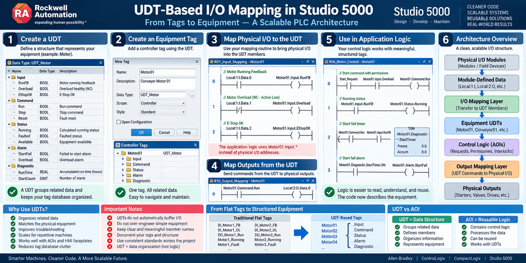
What Is a UDT?
UDT means:
User-Defined Data Type
A UDT allows the programmer to define a custom structure containing multiple members.
For example:
UDT_Motorcould contain:
RunFB
Overload
RunCmd
Running
Faulted
StartFail
Instead of creating six unrelated controller tags, we can create one tag:
Motor01with the data type:
UDT_MotorThe members are then accessed as:
Motor01.RunFB
Motor01.Overload
Motor01.RunCmd
Motor01.Running
Motor01.Faulted
Motor01.StartFail
Rockwell describes a UDT as a custom data structure that can contain named members of different data types to match a machine or process.
Why This Matters
Compare these two architectures.
Flat Tags
DI_Conv1_PE
DI_Conv1_MotorFB
DI_Conv1_OL
DO_Conv1_Run
Conv1_Running
Conv1_Fault
Conv1_StartFail
Conv1_RunHours
Now imagine:
Conv2
Conv3
Conv4
Conv5
Conv6
The controller tag database becomes increasingly large and repetitive.
UDT Architecture
Instead, create:
Conveyor01with members such as:
Conveyor01.Input.Photoeye
Conveyor01.Input.MotorFB
Conveyor01.Input.Overload

Conveyor01.Command.Run

Conveyor01.Status.Running
Conveyor01.Status.Faulted

Conveyor01.Alarm.StartFail
Now the program begins to describe the equipment rather than simply listing unrelated variables.
A Simple Motor UDT
We could create:
UDT_Motorwith the following members:
| Member | Data Type | Purpose |
|---|---|---|
| RunFB | BOOL | Motor running feedback |
| Overload | BOOL | Motor overload status |
| RunCmd | BOOL | Run command |
| Running | BOOL | Calculated running status |
| Faulted | BOOL | Motor fault status |
| StartFail | BOOL | Motor failed to start |
| RunTime | REAL | Accumulated runtime |
Then create:
Motor01as:
UDT_MotorThe controller now automatically provides:
Motor01.RunFB
Motor01.Overload
Motor01.RunCmd
Motor01.Running
Motor01.Faulted
Motor01.StartFail
Motor01.RunTime
Creating a UDT in Studio 5000
In Studio 5000 Logix Designer:
Controller Organizer
      ↓
Data Types
      ↓
User-Defined
      ↓
New Data Type
Depending on the Studio 5000 version, you may also see the Data Types folder under the Assets section.
Create:
UDT_MotorThen define the members.
For example:
Name          Data Type

RunFB         BOOL
Overload      BOOL
RunCmd        BOOL
Running       BOOL
Faulted       BOOL
StartFail     BOOL
RunTime       REAL
Each member can also have its own description.
Good descriptions are important.
For example:
RunFB
Motor running feedback from starter or VFD
and:
StartFail
Motor run command active but running feedback not received
within allowed start time
Now the UDT begins to document the equipment.
Creating a Tag From the UDT
After creating:
UDT_Motorcreate a new tag:
Motor01with:
Data Type = UDT_MotorNow Studio 5000 automatically creates the entire structure.
You can expand:
Motor01and see all the members underneath it.
Mapping Physical I/O Into a UDT
Now we can connect physical I/O to the equipment structure.
Suppose:
Local:1:I.Data.0is the motor running feedback.
And:
Local:1:I.Data.1is the overload signal.
We could map them as:
Local:1:I.Data.0
------] [----------------------------( )------
                                  Motor01.RunFB
and:
Local:1:I.Data.1
------] [----------------------------( )------
                               Motor01.Overload
Then the motor logic uses:
Motor01.RunFB
Motor01.Overload
instead of physical module references.
Mapping the Output
The application logic may generate:
Motor01.RunCmdThen the output mapping routine writes that command to:
Local:2:O.Data.0For example:
Motor01.RunCmd
------] [----------------------------( )------
                            Local:2:O.Data.0
Now the complete architecture becomes:
Physical Inputs
      ↓
I/O Mapping
      ↓
Motor01.Input / Status
      ↓
Control Logic
      ↓
Motor01.RunCmd
      ↓
Output Mapping
      ↓
Physical Output
Should Inputs, Commands, and Status Be Grouped?
This is where UDT design becomes interesting.
Instead of a flat UDT:
Motor01.RunFB
Motor01.Overload
Motor01.RunCmd
Motor01.Running
Motor01.Faulted
we can create a more organized structure.
For example:
Motor01.Input.RunFB
Motor01.Input.Overload

Motor01.Command.Run
Motor01.Command.Reset

Motor01.Status.Running
Motor01.Status.Faulted

Motor01.Alarm.StartFail
This is much easier to understand.
The structure begins to communicate intent.
Nested UDTs
This is possible because a UDT member can itself use another structured data type.
For example:
UDT_Motor_Inputcontains:
RunFB
Overload
Ready
Then:
UDT_Motor_Commandcontains:
Run
Stop
Reset
Then:
UDT_Motor_Statuscontains:
Running
Stopped
Faulted
Available
Finally:
UDT_Motorcontains:
Input      UDT_Motor_Input
Command    UDT_Motor_Command
Status     UDT_Motor_Status
Now:
Motor01.Input.RunFB
Motor01.Command.Run
Motor01.Status.Running
becomes possible.
This is a very clean architecture.
Do Not Over-Engineer the First UDT
There is an important warning.
Just because nested structures are possible does not mean every simple motor needs ten nested UDTs.
For a small machine:
Motor01.RunFB
Motor01.Overload
Motor01.RunCmd
Motor01.Running
Motor01.Faulted
may be completely sufficient.
For a large plant standard:
Motor01.Input.RunFB
Motor01.Command.Run
Motor01.Status.Running
Motor01.Alarm.StartFail
Motor01.Diagnostic.StartTimer
may be appropriate.
The structure should match the complexity of the equipment.
UDTs and I/O Mapping Are Not the Same Thing
Another important distinction:
A UDT organizes data.
It does not automatically buffer physical I/O.
Suppose:
Motor01.RunFBis created as an Alias directly to:
Local:1:I.Data.0Then the UDT member may still effectively point toward physical I/O.
If instead we execute:
Local:1:I.Data.0
        ↓
Mapping Logic
        ↓
Motor01.RunFB
then we have created an independent application value.
So once again:
UDTdoes not automatically mean:
BufferUDT architecture and I/O buffering are related concepts, but they solve different problems.
Module-Defined Data Types vs User-Defined Data Types
Studio 5000 also creates structured tags automatically for many devices.
For example, when an I/O module is added, Studio 5000 may create tags such as:
Local:1:I
Local:1:O
Local:1:C
These are based on:
Module-Defined Data Types
The module manufacturer defines their structure.
Rockwell distinguishes these from UDTs: module-defined data types are created by the module and hold its input, output, or configuration data; UDTs are custom structures created by the programmer.
Conceptually:
MODULE-DEFINED DATA
        ↓
Programmer Mapping
        ↓
USER-DEFINED DATA
That is a very powerful architecture.
Example With a VFD
This becomes even more useful with a PowerFlex drive.
The physical/network device may expose values such as:
Drive Ready
Drive Active
Drive Faulted
Output Frequency
Output Current
Command Frequency
Instead of spreading those values throughout the PLC program, create:
VFD01with:
VFD01.Input.Ready
VFD01.Input.Running
VFD01.Input.Faulted

VFD01.Feedback.Frequency
VFD01.Feedback.Current

VFD01.Command.Run
VFD01.Command.Reset
VFD01.Command.SpeedRef

VFD01.Status.Available
Now all data associated with that VFD is grouped together.
Why Technicians Benefit
Imagine troubleshooting:
VFD01You expand the tag and immediately see:
Input
Command
Feedback
Status
Alarm
Instead of searching through hundreds of unrelated controller tags.
That reduces troubleshooting time.
The PLC database begins to resemble the actual machine.
Example Conveyor UDT
A conveyor might use:
UDT_Conveyorwith:
Input.StartPB
Input.StopPB
Input.Photoeye
Input.MotorFB
Input.Overload

Command.Run

Status.Running
Status.Stopped
Status.Blocked
Status.Faulted

Alarm.StartFail
Alarm.Overload

Timer.StartDelay
Timer.StopDelay
Then:
Conveyor01
Conveyor02
Conveyor03
can all use the same structure.
This Is Where Scalability Begins
Imagine ten conveyors.
Without UDTs:
Conv1_PE
Conv1_FB
Conv1_OL
Conv1_Run
Conv1_Fault

Conv2_PE
Conv2_FB
Conv2_OL
Conv2_Run
Conv2_Fault

Conv3_PE
...
With a UDT:
Conveyor01
Conveyor02
Conveyor03
Conveyor04
...
Conveyor10
Each has the same members.
This creates consistency across the program.
Arrays of UDTs
We can go another step further.
Instead of:
Conveyor01
Conveyor02
Conveyor03
we could create:
Conveyor[10]where each array element is:
UDT_ConveyorThen:
Conveyor[0].Command.Run
Conveyor[1].Command.Run
Conveyor[2].Command.Run
This can be extremely useful in repetitive systems.
But arrays of UDTs also require good documentation.
A technician needs to know:
Conveyor[0] = Infeed Conveyor
Conveyor[1] = Transfer Conveyor
Conveyor[2] = Discharge Conveyor
Otherwise the structure becomes compact but less readable.
UDTs and AOIs
UDTs become even more powerful when combined with:
Add-On Instructions — AOIs
Imagine an AOI:
AOI_Motorthat processes:
Motor01The architecture may become:
Physical I/O
      ↓
Mapping
      ↓
Motor01 UDT
      ↓
AOI_Motor
      ↓
Motor01 Status / Commands
      ↓
Output Mapping
This is where reusable object-oriented-like PLC architecture begins to appear.
A motor can be standardized once and reused many times.
Important: UDT and AOI Are Different
Do not confuse them.
A:
UDTdefines:
Data structure
An:
AOIdefines:
Reusable logic or behavior
Simple mental model:
UDT = DATA
AOI = LOGIC
When combined:
UDT + AOIcan represent an equipment object.
Example
The UDT stores:
Motor01.Input.RunFB
Motor01.Input.Overload
Motor01.Command.Run
Motor01.Status.Running
Motor01.Status.Faulted
The AOI evaluates:
Run Request
Permissives
Feedback
Start Timeout
Fault Reset
and updates the motor structure.
This can produce highly reusable control code.
UDT-Based I/O Layer
We can now expand the architecture developed throughout this series:
┌──────────────────────────────┐
│ Physical I/O Modules         │
└─────────────┬────────────────┘
              ↓
┌──────────────────────────────┐
│ Module-Defined Data          │
└─────────────┬────────────────┘
              ↓
┌──────────────────────────────┐
│ I/O Mapping Layer            │
└─────────────┬────────────────┘
              ↓
┌──────────────────────────────┐
│ Equipment UDTs               │
│ Motor01 / Valve01 / VFD01    │
└─────────────┬────────────────┘
              ↓
┌──────────────────────────────┐
│ Control Logic / AOIs         │
└─────────────┬────────────────┘
              ↓
┌──────────────────────────────┐
│ Commands                     │
└─────────────┬────────────────┘
              ↓
┌──────────────────────────────┐
│ Output Mapping               │
└─────────────┬────────────────┘
              ↓
┌──────────────────────────────┐
│ Physical Outputs             │
└──────────────────────────────┘
The software architecture now closely mirrors the physical machine.
Example: Motor From Field to Logic
Suppose:
Local:1:I.Data.0is:
Motor Running Feedbackand:
Local:1:I.Data.1is:
Motor Overload HealthyInput mapping:
Local:1:I.Data.0
        ↓
Motor01.Input.RunFB
Local:1:I.Data.1
↓
Motor01.Input.OL_OKControl logic determines:
Motor01.Command.RunThen output mapping:
Motor01.Command.Run
        ↓
Local:2:O.Data.0
The application logic never needs to know:
Local:1:I.Data.0
Local:1:I.Data.1
Local:2:O.Data.0
It understands only:
Motor01That is hardware abstraction.
Troubleshooting Path
Suppose Motor01 will not start.
The technician can expand:
Motor01and check:
Inputs
Motor01.Input.RunFB
Motor01.Input.OL_OK
Command
Motor01.Command.RunStatus
Motor01.Status.Available
Motor01.Status.Running
Motor01.Status.Faulted
Alarms
Motor01.Alarm.StartFail
Motor01.Alarm.Overload
Now troubleshooting follows the equipment instead of requiring a search across the controller database.
Physical I/O Should Still Be Easy to Find
One possible danger of UDT architecture is hiding the physical source too deeply.
A technician should still be able to answer:
Which input card and channel provides Motor01.RunFB?
That is why a dedicated mapping routine remains valuable.
For example:
R01_Input_Mappingshows:
Local:1:I.Data.0 → Motor01.Input.RunFB
Local:1:I.Data.1 → Motor01.Input.OL_OK
The UDT organizes the application.
The mapping routine documents the hardware relationship.
Both layers are useful.
Do Not Mix Raw I/O and Calculated Status
Another design decision is deciding what belongs in the UDT.
For example:
Motor01.Input.RunFBis raw/mapped input.
But:
Motor01.Status.Runningmay be calculated logic.
These should not mean exactly the same thing.
A useful philosophy is:
Inputrepresents information coming into the equipment object.
Commandrepresents what the controller wants the equipment to do.
Statusrepresents interpreted equipment state.
Alarmrepresents abnormal conditions.
This separation becomes extremely useful.
Example
Suppose:
Motor01.Command.Run = 1but:
Motor01.Input.RunFB = 0for five seconds.
The control logic may determine:
Motor01.Status.Running = 0
Motor01.Status.Faulted = 1
Motor01.Alarm.StartFail = 1
This demonstrates why:
Input.RunFBand:
Status.Runningshould not automatically be treated as the same signal.
Equipment-Oriented Naming
A strong UDT architecture follows the actual equipment.
Examples:
Motor01
Valve01
Pump01
Conveyor01
Tank01
VFD01
AnalogInput01
Then members describe function:
.Input
.Command
.Status
.Alarm
.Config
.Diagnostic
For example:
Pump01.Input.RunFB
Pump01.Command.Start
Pump01.Status.Running
Pump01.Alarm.StartFail
Pump01.Config.StartTimeout
This is far easier to understand than hundreds of unrelated tags.
Configuration Members
UDTs can also contain configuration values.
For example:
Motor01.Config.StartTimeout
Motor01.Config.StopTimeout
or:
Tank01.Config.HighLimit
Tank01.Config.LowLimit
This groups configuration with the equipment it affects.
But use caution.
Not every constant in the program needs to be buried inside a giant UDT.
Again:
Organization should improve understanding, not create unnecessary complexity.
Diagnostic Members
Diagnostics are another strong use case.
For example:
Motor01.Diagnostic.StartTimer
Motor01.Diagnostic.StopTimer
Motor01.Diagnostic.RunHours
Motor01.Diagnostic.StartCount
This allows maintenance information to remain associated with the motor.
For a technician, this can be extremely useful.
HMI Integration
Structured tags can also make HMI design easier.
Instead of connecting an HMI object to:
Motor1_Run
Motor1_Fault
Motor1_Available
Motor1_StartCmd
the HMI can conceptually reference:
Motor01.Command.Run
Motor01.Status.Running
Motor01.Status.Faulted
Motor01.Status.Available
When equipment structures are consistent, reusable HMI faceplates become much easier to build.
External Access
When designing UDTs, also consider which data really needs to be available outside the controller.
Studio 5000 allows external access settings for tags and data type members, which can affect access from applications such as HMIs.
Not every diagnostic or internal member needs to be exposed externally.
That becomes increasingly important as projects grow.
Memory Considerations
UDTs organize memory; they do not eliminate memory usage.
A structure can contain:
BOOL
DINT
REAL
Arrays
Nested Structures
and the resulting tag occupies memory according to the structure layout.
Rockwell notes that structure tags occupy contiguous controller memory, with the members arranged in sequence.
Therefore, very large UDTs multiplied hundreds of times can consume meaningful controller memory.
For example:
UDT_Device = 500 bytesand:
Device[500]would represent approximately:
250,000 bytesbefore considering other controller resources.
This does not mean large UDTs are bad.
It means they should be intentional.
Avoid the “Mega UDT”
One common design mistake is creating one enormous UDT containing everything imaginable:
100 Inputs
100 Outputs
50 Timers
40 Alarms
30 Configuration Values
20 Arrays
Diagnostics
HMI
Simulation
Maintenance
Recipes
for a simple motor.
That may technically work.
But it can create unnecessary complexity and memory use.
The goal is not:
Put everything into a UDT.
The goal is:
Group data that logically belongs together.
Another Common Mistake: Generic Names
Avoid structures such as:
Device01.Data1
Device01.Data2
Device01.Bit1
Device01.Bit2
These defeat one of the biggest benefits of UDTs.
Better:
Motor01.Input.RunFB
Motor01.Input.Overload
Motor01.Command.Run
Motor01.Status.Faulted
The tag path should help explain the machine.
UDT Naming Example
A practical naming convention might be:
UDT_Motor
UDT_Valve
UDT_Conveyor
UDT_VFD
UDT_AnalogInput
Instances:
Motor01
Valve01
Conveyor01
VFD01
TankLevel
Members:
.Input
.Command
.Status
.Alarm
.Config
.Diagnostic
This provides a predictable architecture.
UDTs and COP/CPS
The previous article discussed copying structures.
UDTs are structures.
Therefore, COP or CPS can sometimes be used with UDT-based data.
For example:
CPS
Source: Motor01
Dest: Motor01_Snapshot
Length: 1
could conceptually create a synchronized snapshot of the structure when required.
However:
Do not automatically copy every UDT with COP or CPS.
The same rules still apply:
- Understand the memory layout
- Understand Length
- Understand data ownership
- Determine whether synchronization is actually necessary
A UDT does not change those requirements.
UDTs Do Not Replace Good Logic Structure
Another important point:
Creating:
Motor01.Command.Rundoes not automatically mean the motor logic is well designed.
You still need:
Requests
Permissives
Interlocks
Commands
Feedback
Faults
Alarms
The UDT organizes the data.
The program architecture organizes the behavior.
Both are required.
Example Industrial Structure
A larger machine could use:
MainRoutine

R01_Input_Mapping
R02_Process_Status
R03_Requests
R04_Permissives
R05_Interlocks
R06_Equipment_Control
R07_Faults
R08_Alarms
R09_HMI_Status
R10_Output_Mapping
with equipment tags such as:
Motor01
Motor02
VFD01
Valve01
Valve02
Conveyor01
Tank01
Now each routine works with structured equipment data.
Flat Tags vs UDTs
A practical comparison:
| Feature | Flat Tags | UDT-Based Tags |
|---|---|---|
| Simple for very small projects | Excellent | Good |
| Tag organization | Moderate | Excellent |
| Repetitive equipment | Poor | Excellent |
| Scalability | Moderate | Excellent |
| Troubleshooting by equipment | Moderate | Excellent |
| AOI integration | Good | Excellent |
| HMI standardization | Moderate | Excellent |
| Initial design effort | Low | Higher |
| Requires naming discipline | Yes | Absolutely |
UDTs become more valuable as the project grows.
When Should You Use a UDT?
UDTs are especially useful when:
- Multiple devices share similar data
- Equipment has several related statuses
- You want reusable AOIs
- You are building standardized HMI objects
- The project has repeated motors, valves, conveyors, or drives
- The controller tag database is becoming difficult to navigate
- You want equipment-oriented architecture
When Might a UDT Be Unnecessary?
If a machine contains:
3 Inputs
2 Outputs
1 Motor
creating a complex hierarchy of nested structures may not provide much benefit.
Sometimes:
DI_Start
DI_Stop
DO_Motor
is completely adequate.
Good engineering is not about maximizing complexity.
It is about using enough structure to make the system understandable and maintainable.
Practical Design Rule
A useful rule is:
If several tags always describe the same piece of equipment, consider grouping them.
For example:
Motor_RunFB
Motor_OL
Motor_RunCmd
Motor_Fault
probably belong together.
Likewise:
Valve_OpenFB
Valve_ClosedFB
Valve_OpenCmd
Valve_CloseCmd
Valve_Fault
probably belong together.
That is exactly the type of problem UDTs solve well.
From Tags to Equipment Objects
This represents an important evolution in PLC programming.
We begin with:
Local:1:I.Data.0Then:
DI_Motor_FBThen:
Motor01.RunFBThen:
Motor01.Input.RunFBEventually, combined with an AOI:
Motor01
        ↓
AOI_Motor
The programming model evolves from:
Individual bits
toward:
Equipment objects
That is a major step in modern PLC architecture.
The Technician’s Perspective
A well-designed UDT should help the technician answer questions quickly.
For a motor:
Motor01the technician should be able to determine:
Is it being commanded?

Is the feedback present?

Is an overload active?

Is it available?

Is it faulted?

Why did it fail to start?
without searching through dozens of unrelated tags.
If the UDT makes those questions easier to answer, it is doing its job.
Final Thought
UDTs do not make a PLC program industrial simply because they are being used.
A poorly designed UDT can make a program more confusing.
A well-designed UDT creates a predictable relationship between:
Physical Equipment
        ↓
Structured Data
        ↓
Control Logic
The real value is organization.
Instead of hundreds of unrelated tags:
Motor1_FB
Motor1_OL
Motor1_Run
Motor1_Fault
we can represent the equipment itself:
Motor01.Input.RunFB
Motor01.Input.Overload
Motor01.Command.Run
Motor01.Status.Faulted
The PLC program begins to look like the machine it controls.
And once the data is organized this way, the next logical step is to combine structured data with reusable logic.
That is where:
UDT + AOIbecomes extremely powerful.
Next Article
Digital I/O Buffering in Studio 5000 — From Field Signals to Clean Application Logic
In the next article, we will return to the physical I/O layer and build a complete digital input and output buffering strategy.
We will follow signals through:
Field Device
      ↓
Physical Input
      ↓
Raw Input Mapping
      ↓
Signal Validation
      ↓
Application Tag / UDT
      ↓
Control Logic
      ↓
Output Command
      ↓
Output Mapping
      ↓
Field Device
We will also examine:
- Normally open vs normally closed signals
- Fail-safe input philosophy
- Electrical state vs process meaning
- Debounce vs buffering
- Motor feedback
- Overload signals
- Photoeyes
- Limit switches
- Output ownership
- Simulation-friendly mapping
This is where the entire I/O architecture begins to come together.