Why Hardwired E-Stops Matter
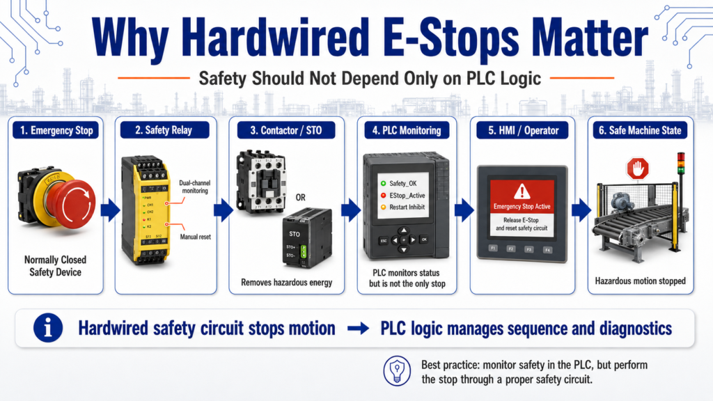
Safety Should Not Depend Only on PLC Logic
In industrial automation, an Emergency Stop is one of the most important safety devices on a machine. It is not just another push button. It is designed to stop hazardous motion or remove energy when an unsafe condition occurs.
A common beginner mistake is thinking that an E-Stop should simply be wired into a PLC input and handled only by ladder logic.
In real industrial control systems, that is not the best approach.
An Emergency Stop should be hardwired through a proper safety circuit, not only programmed in the PLC.
A hardwired emergency stop circuit is recommended because it provides a redundant method of stopping output signals that is independent of the PLC program.
1. What Is an E-Stop?
E-Stop stands for Emergency Stop.
Its purpose is to stop equipment quickly when there is a potential hazard to people, equipment, or the process.
An E-Stop may be used when:
- A person is in danger
- A machine is moving unexpectedly
- A jam creates a hazardous condition
- A guard is open
- Equipment is behaving abnormally
- The operator needs to stop the machine immediately
The key idea is simple:
The E-Stop is for emergency conditions, not normal machine stopping.
A normal stop button is part of the operating sequence.
An E-Stop is part of the safety system.
2. Normal Stop vs Emergency Stop
A normal stop and an emergency stop may both stop a machine, but they are not the same.
| Function | Normal Stop | Emergency Stop |
|---|---|---|
| Purpose | Stop the process normally | Stop hazardous motion or unsafe operation |
| Used for | Routine operation | Emergency condition |
| Controlled by | PLC logic or control circuit | Safety-rated or hardwired safety circuit |
| Reset required | Usually simple restart | Usually requires manual reset |
| Safety role | Operational control | Personnel and equipment protection |
A normal stop can be controlled by the PLC sequence.
An E-Stop must be treated with a higher level of importance.
3. Why Not Use Only PLC Logic?
A PLC is excellent for controlling a process, but a standard PLC program should not be the only thing stopping hazardous motion.
Why?
Because PLC logic depends on several things working correctly:
- PLC processor
- Program scan
- Input module
- Output module
- Output wiring
- Program logic
- Communication
- Power supply
- Controller mode
- Correct program execution
If any of those fail, a software-only E-Stop may not stop the machine as expected.
That is why hardwired safety circuits exist.
A hard-wired emergency stop circuit is desirable and installing a hard-wired emergency stop circuit on a programmable controller.
4. What Does “Hardwired” Mean?
A hardwired E-Stop means the E-Stop device is wired directly into a safety control circuit instead of depending only on PLC logic.
A simple concept looks like this:
E-Stop Button
      ↓
Safety Relay / Safety Controller
      ↓
Contactor / Drive Enable / Output Power
      ↓
Machine Motion Stops
The PLC may still monitor the E-Stop status, but the PLC is not the only device responsible for removing the hazardous motion.
That distinction matters.
5. The PLC Can Monitor the E-Stop, But Should Not Be the Only Control
In many industrial machines, the PLC receives a safety status input such as:
Safety_OK
EStop_Reset_OK
Guard_Closed
Safety_Relay_Healthy
The PLC can use this input to:
- Stop the automatic sequence
- Display an alarm on the HMI
- Prevent restart
- Show operator messages
- Log the event
- Require a reset sequence
But the actual safety function should be handled by a proper hardwired safety circuit.
A good way to think about it is:
Safety circuit = removes hazardous energy
PLC logic = manages sequence and operator information
6. Basic E-Stop Control Philosophy
A practical safety philosophy looks like this:
E-Stop Healthy
      ↓
Safety Relay Energized
      ↓
Motor Control Power Available
      ↓
PLC Sees Safety_OK
      ↓
Machine Allowed to Run
When the E-Stop is pressed:
E-Stop Pressed
      ↓
Safety Relay Drops Out
      ↓
Motor Control Power Removed
      ↓
PLC Sees Safety_OK = False
      ↓
Machine Sequence Stops
      ↓
HMI Displays Safety Fault
This gives the system two layers:
- Hardwired safety action
- PLC logic response
That is much better than depending only on ladder logic.
7. Normally Closed E-Stop Contacts
E-Stops are commonly wired using normally closed contacts.
Why?
Because a normally closed circuit is fail-safe for many basic control applications.
If the wire breaks, the contact opens, or the device is disconnected, the circuit drops out.
Simple idea:
Healthy condition = circuit closed
Unsafe condition = circuit open
Broken wire = circuit open
This is why E-Stop chains and stop circuits are often designed to open the control circuit when there is a problem.
8. Safety Relay or Safety Controller
In modern systems, E-Stops are often wired to a safety relay or safety controller.
The safety device may monitor:
- E-Stop channels
- Guard switches
- Light curtains
- Safety mats
- Reset button
- Feedback from contactors
- Faults between dual channels
The safety relay can then control:
- Motor contactor coils
- Drive enable circuits
- Safety contactors
- STO input on a VFD or servo drive
- Control power to hazardous outputs
This is more reliable than treating the E-Stop as a regular input.
9. What Should the PLC Do After an E-Stop?
When an E-Stop is pressed, the PLC should not just restart automatically when the E-Stop is released.
A safer control approach is:
- Detect that the safety circuit dropped.
- Stop the machine sequence.
- Drop run commands.
- Show a clear HMI message.
- Require the operator to release the E-Stop.
- Require safety reset if applicable.
- Require a normal Start command to restart.
Example PLC behavior:
IF Safety_OK = False THEN
    Stop all automatic sequence commands
    Drop motor run requests
    Set safety alarm
    Inhibit restart
END_IF
The safety circuit removes hazardous energy.
The PLC prevents the machine sequence from continuing unexpectedly.
10. E-Stop Should Not Be Used as a Normal Stop
Operators sometimes use the E-Stop as a normal stop button. That is not a good habit.
The E-Stop is for emergency situations.
For normal operation, the machine should have a normal stop button or HMI stop command.
Using the E-Stop for routine stopping can cause:
- Unnecessary safety faults
- Production delays
- Drive faults
- Loss of sequence position
- Mechanical stress
- More complicated restarts
A good HMI and panel design should make the normal Stop button easy to find and understand.
11. What Should the HMI Show?
When an E-Stop is active, the HMI should clearly tell the operator what happened.
Good HMI messages:
Emergency Stop Active
Release E-Stop and press Safety Reset.
Safety Circuit Not Healthy
Check E-Stops, guards, and safety relay status.Machine Restart Inhibited
Restore safety circuit and press Start.The HMI should not simply say:
FaultThat is not enough information for the operator or technician.
12. Panel Indicators for E-Stop Conditions
A good control panel may include:
| Indicator | Purpose |
|---|---|
| E-Stop Active | Shows emergency stop condition |
| Safety Relay Healthy | Shows safety circuit status |
| Safety Reset Required | Tells operator reset is needed |
| Machine Ready | Shows machine can be started |
| Fault Active | Shows troubleshooting is required |
These indicators help operators and technicians understand the machine state quickly.
13. Technician Troubleshooting Mindset
When troubleshooting an E-Stop circuit, do not start by changing ladder logic.
Start with the safety circuit.
Check:
- Is the E-Stop button pressed?
- Is the E-Stop mechanically latched?
- Are all E-Stops released?
- Are guard doors closed?
- Is the safety relay powered?
- Are both safety channels healthy?
- Is the reset circuit working?
- Are contactor feedback contacts closed?
- Is 24 VDC present?
- Is the PLC receiving the Safety_OK input?
The troubleshooting material also reinforces a systematic approach: recognize the symptom, isolate the problem, and take corrective action.
That same method applies perfectly to E-Stop troubleshooting.
14. Simple Ladder Logic Concept for Safety Status
The PLC should use the safety circuit status as a permissive.
Example:
Safety_OK
AND No_Faults
AND Auto_Mode
AND Start_Request
THEN Machine_Run_Permissive
Better tag names:
DI_Safety_Relay_OK
DI_EStop_Circuit_OK
Safety_OK
Machine_Run_Permissive
Restart_Inhibited
Safety_Reset_Required
The final output should not depend only on the E-Stop input. The physical safety circuit should already remove power or disable hazardous motion.
The PLC logic should make sure the sequence does not restart incorrectly.
15. Common Beginner Mistakes
Mistake 1: Wiring the E-Stop only to a PLC input
This may tell the PLC that the E-Stop was pressed, but it may not remove hazardous energy if the PLC or output fails.
Mistake 2: Allowing automatic restart after E-Stop release
Releasing the E-Stop should not automatically restart the machine. A deliberate reset and start action should be required.
Mistake 3: Using E-Stop as a normal stop
This creates unnecessary downtime and can make operators ignore proper machine operation.
Mistake 4: Not showing useful HMI messages
Operators need clear instructions, not vague alarms.
Mistake 5: Bypassing safety devices during troubleshooting
Never bypass safety devices casually. Any bypass must follow proper plant procedures, risk assessment, and authorization.
Final Thoughts
Hardwired E-Stops matter because safety should not depend only on PLC logic.
A PLC is excellent for sequencing, alarms, diagnostics, and machine control, but hazardous motion should be stopped through a proper safety circuit.
A strong design separates the responsibilities:
Hardwired safety circuit = stops hazardous motion
PLC logic = monitors safety status and controls the sequence
HMI = informs the operator what happened
For a beginner in industrial automation, this is one of the most important lessons to understand:
The PLC can monitor safety, but the safety circuit must be able to act independently.
That mindset is closer to real industrial practice and helps build safer, more professional control systems.