Understanding PLC I/O Modules
How PLCs Connect to the Real World
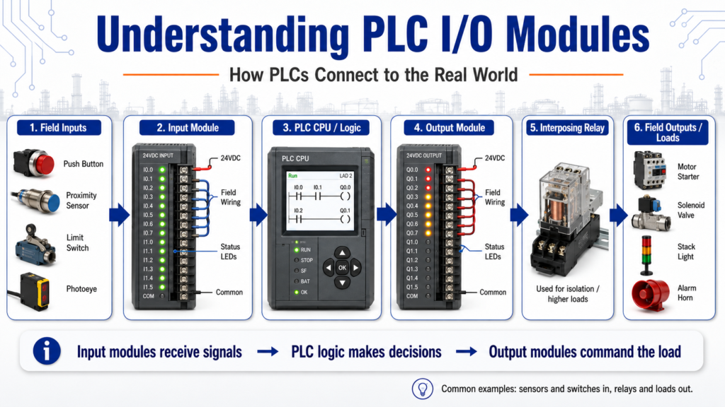
A PLC does not control a machine by itself. It needs a way to receive signals from field devices and send commands back to the equipment. That is the job of the I/O modules.
In simple terms:
Input modules bring information into the PLC.
Output modules send commands from the PLC to the machine.
Input/output modules as the “eyes, ears, and hands” of a programmable controller because they connect real-world sensing devices and work devices to the control system.
That is one of the best ways to understand I/O:
Field Devices → Input Module → CPU / Logic → Output Module → Machine Action1. What Does I/O Mean?
I/O stands for Input / Output.
Inputs are signals coming into the PLC.
Outputs are signals going out of the PLC.
Examples:
| Type | Examples |
|---|---|
| Inputs | Push buttons, selector switches, proximity sensors, photoeyes, limit switches, pressure switches |
| Outputs | Motor starters, relays, solenoids, stack lights, alarm horns, contactors, VFD run commands |
The answer key explains that the I/O section communicates with field devices by receiving signals from devices such as limit switches and proximity sensors, while outputs send signals to devices such as motor starters, relays, and solenoids.
In real industrial troubleshooting, this is very important because the problem may not be in the ladder logic. It may be in the field device, the wiring, the I/O module, or the output load.
2. Input Modules
An input module receives signals from the machine or process.
Common input signals include:
- Push button pressed
- Selector switch position
- Limit switch made
- Proximity sensor detecting metal
- Photoeye detecting a product
- Pressure switch made
- Level switch made
- Motor overload contact status
- Safety relay feedback
The PLC input module converts these real-world electrical signals into data the CPU can read.
Example:
Proximity Sensor Detects Box
        ↓
24 VDC signal goes to input terminal
        ↓
Input module LED turns ON
        ↓
PLC input bit becomes TRUE
        ↓
Logic uses that condition
A very common troubleshooting question is:
The sensor is ON, but does the PLC actually see it?
You should check both:
- The physical sensor
- The PLC input LED / input bit
3. Output Modules
An output module sends signals from the PLC to field devices.
Common output devices include:
- Motor starter coil
- Interposing relay
- Solenoid valve
- Stack light
- Alarm horn
- Contactor coil
- VFD digital input
- Pilot light
Example:
PLC Logic Enables Conveyor_Run
        ↓
Output bit turns TRUE
        ↓
Output module LED turns ON
        ↓
Voltage is sent to the field device
        ↓
Motor starter energizes
        ↓
Conveyor runs
The important point is this:
A PLC output bit turning ON in the software does not always mean the machine device actually worked.
You still need to verify:
- Output LED
- Output terminal voltage
- Fuse
- Relay
- Load power
- Field wiring
- Device coil
- Mechanical response
4. AC and DC I/O Modules
PLC I/O modules are available in different voltage types.
Common examples include:
| Module Type | Common Use |
|---|---|
| 24 VDC input | Sensors, push buttons, safety feedback |
| 120 VAC input | Older control circuits, field switches |
| 24 VDC output | Relays, solenoids, indicators, VFD inputs |
| 120 VAC output | AC coils, pilot lights, some older devices |
| Relay output | Isolated switching for different voltages |
| Analog input | Pressure, temperature, level, flow |
| Analog output | Valve position, speed reference, control signal |
How basic AC/DC input and output modules work and understanding proper voltage connections for input and output modules.
For a technician, this matters because using the wrong voltage or wiring type can damage equipment or create confusing troubleshooting symptoms.
5. Optical Isolation
Many I/O modules use optical isolation.
Optical isolation helps protect the PLC electronics from electrical noise, voltage spikes, and transient voltages from the field wiring.
The answer key gives two reasons for optical isolation:
- To protect the CPU from transient voltages and spikes.
- To convert high-voltage field signals to a level the processor can handle.
In simple words:
Optical isolation creates a safer electrical separation between the dirty field side and the sensitive PLC electronics.
This is especially important in industrial environments where motors, contactors, solenoids, VFDs, and long cable runs can introduce electrical noise.
6. Interposing Relays
An interposing relay is a relay placed between the PLC output and the final load.
It is commonly used when:
- The load current is too high for the PLC output
- The field device uses a different voltage
- The technician wants extra electrical isolation
- The output module needs protection
- The load is inductive, such as a coil or solenoid
The answer key explains that an interposing relay is used to handle output loads larger than what the PLC output can handle and to isolate the output device from the PLC.
Example:
PLC Output
   ↓
Interposing Relay Coil
   ↓
Relay Contact
   ↓
Solenoid / Contactor / Field Device
This is a very common design in control panels.
7. Shielding, Grounding, and EMI
Industrial panels can be electrically noisy.
Common noise sources include:
- VFDs
- Motors
- Contactors
- Solenoids
- Long cable runs
- Poor grounding
- High-current wiring near signal wiring
I/O shielding, grounding, surge suppression, and EMI. It also states that electromagnetic induction can be reduced with proper grounding of equipment.
Good wiring practices include:
- Separate high-voltage and low-voltage wiring
- Separate VFD motor leads from signal wiring
- Use shielded cable where required
- Ground shields correctly according to plant standard and manufacturer documentation
- Keep analog signals away from noisy power wiring
- Use proper surge suppression on coils
- Keep terminals tight and clean
For troubleshooting, noise problems may appear as:
- Flickering inputs
- False sensor triggers
- Unstable analog values
- Random faults
- Communication errors
- Outputs behaving unexpectedly
8. Surge Suppression
Inductive devices can create voltage spikes when they turn off.
Examples:
- Relay coils
- Solenoid coils
- Contactor coils
- Motor starter coils
Surge suppression helps protect PLC output modules and other control components from these voltage spikes.
Common suppression methods include:
| Load Type | Common Suppression |
|---|---|
| DC coil | Flyback diode |
| AC coil | RC snubber or MOV |
| Relay output | Suppressor across coil/load |
| Solenoid | Diode, MOV, or surge suppressor depending on voltage |
This is one of those details that separates basic wiring from more professional industrial control design.
9. Hardwired Emergency Stop Circuits
A very important point:
An Emergency Stop should not depend only on PLC logic.
The answer key explains that a hardwired emergency stop circuit is recommended because it provides a redundant method of stopping all output signals independent of the PLC program.
In real systems, the E-Stop circuit may remove control power from output devices, drop out a safety relay, or remove power from contactors depending on the safety design.
The PLC can monitor the E-Stop status, but the actual safety function should be properly hardwired and designed according to the applicable safety requirements.
Simple concept:
E-Stop Pressed
        ↓
Safety circuit opens
        ↓
Output power is removed
        ↓
Machine motion stops
        ↓
PLC receives safety status input
The PLC should know the safety status, but the PLC should not be the only thing stopping hazardous motion.
10. Solid-State Outputs and Failure Modes
PLC output modules can be relay-based or solid-state.
Solid-state outputs are common because they can switch quickly and do not have mechanical contacts. However, they can fail differently than relay outputs.
Solid-state output devices can fail in a shorted/on condition.
That is important for troubleshooting because an output device may remain energized even when the PLC logic appears to be off.
Always verify the actual voltage and device behavior safely.
11. Troubleshooting PLC Inputs
When troubleshooting an input, follow a structured path.
Example problem:
Sensor is detecting the part, but the PLC does not respond.
Check:
- Is the sensor powered?
- Is the sensor output changing state?
- Is the input LED turning ON?
- Is voltage present at the input terminal?
- Is the correct common connected?
- Is the input module type correct?
- Is the correct address used in the program?
- Is the signal wired normally open or normally closed?
- Is there a blown fuse or broken wire?
- Is the input module healthy?
A good technician proves each step instead of guessing.
12. Troubleshooting PLC Outputs
When troubleshooting an output, follow the command path.
Example problem:
PLC output should turn on a solenoid, but the valve does not actuate.
Check:
- Is the logic enabling the output?
- Is the output bit ON in software?
- Is the output module LED ON?
- Is voltage present at the output terminal?
- Is the fuse good?
- Is the interposing relay energizing?
- Is voltage reaching the solenoid coil?
- Is the coil good?
- Is air pressure available?
- Is the valve mechanically stuck?
This separates electrical, PLC, pneumatic, and mechanical problems.
13. Practical Technician Checklist
Use this checklist when working with I/O modules:
| Check | Why It Matters |
|---|---|
| Correct voltage | Prevents module damage |
| Correct common | Inputs/outputs need a proper return path |
| Input LED | Confirms module sees the field signal |
| Output LED | Confirms logic is commanding the output |
| Terminal voltage | Confirms electrical signal is present |
| Field device status | Confirms the real device is working |
| Fuse / breaker | Common cause of lost control power |
| Wiring condition | Loose or broken wires create intermittent faults |
| Module status | Identifies hardware or communication issues |
| Program address | Wrong address means wrong logic behavior |
14. Common Beginner Mistakes
Here are common mistakes when learning PLC I/O:
Mistake 1: Assuming the sensor is working because the sensor LED is ON
A sensor LED may be ON, but the PLC input may not receive the signal.
Mistake 2: Assuming the output works because the PLC output bit is ON
The output bit can be ON in software, but the module, fuse, relay, wiring, or device may still fail.
Mistake 3: Ignoring the common wire
Many I/O problems are caused by missing or incorrect common wiring.
Mistake 4: Confusing input logic with electrical wiring
A normally closed field device can be programmed with an XIC or XIO depending on the desired logical condition.
Mistake 5: Replacing modules too fast
Always verify field wiring and devices first. Many “bad module” calls are actually wiring, fuse, or device problems.
Final Thoughts
PLC I/O modules are the bridge between the PLC program and the real machine.
Inputs bring field information into the PLC.
Outputs send control commands back to the field devices.
Understanding I/O modules helps with:
- Programming
- Troubleshooting
- Reading schematics
- Testing sensors
- Testing outputs
- Understanding machine behavior
- Finding real root causes
For a beginner, one of the best mental models is this:
Input Module = What the PLC sees
CPU / Logic = What the PLC decides
Output Module = What the PLC commands
Field Device = What actually happens
Once you understand that path, troubleshooting becomes much more logical and much less random.