PLC Scan Cycle Explained
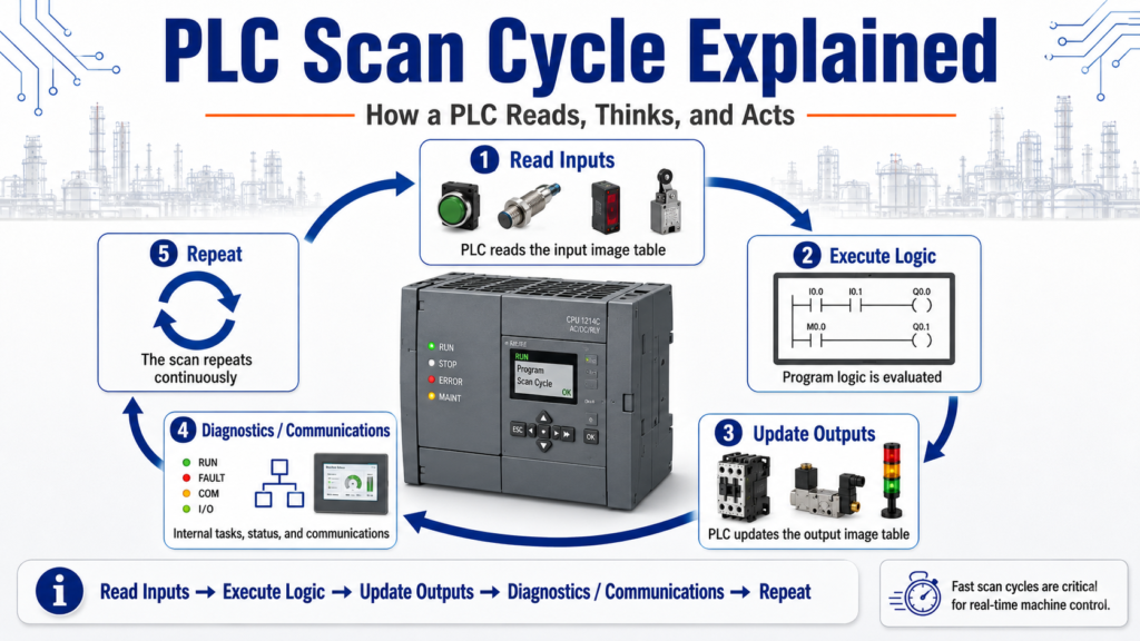
How a PLC Reads, Thinks, and Acts
One of the most important concepts for anyone learning PLCs is the PLC scan cycle.
At first, ladder logic may look like electrical wiring, but a PLC program does not work exactly like a hardwired circuit. A PLC works by scanning its program repeatedly, very fast, over and over again.
In simple terms, a PLC does three main things:
Read Inputs → Execute Logic → Update OutputsThe processor scan as a three-step process: the processor reads the input image table, compares the result to the user program, and then sets the output image table. It also notes that scan order and scan time are important, especially when working with high-speed devices.
1. What Is a PLC Scan Cycle?
A PLC scan cycle is one complete pass through the PLC’s operating routine.
During one scan, the PLC:
- Reads the status of the input devices.
- Executes the ladder logic program.
- Updates the output devices.
- Performs internal tasks such as diagnostics and communication.
Then it repeats the same process again.
This happens continuously while the PLC is in RUN mode.
Scan 1 → Scan 2 → Scan 3 → Scan 4 → Scan 5 → ...This is why PLCs can control machines in real time. They are constantly checking the process and updating outputs based on the logic.
2. Step 1: Read Inputs
The first major step is reading the inputs.
The PLC looks at the status of its input modules and stores that information in memory.
Examples of input conditions:
| Field Device | PLC Sees |
|---|---|
| Start button pressed | Input bit = 1 |
| Stop button healthy | Input bit = 1 |
| Photoeye blocked | Input bit = 1 |
| Limit switch made | Input bit = 1 |
| Overload contact tripped | Input bit = 0 or 1 depending on wiring |
| Safety relay healthy | Input bit = 1 |
A simple example:
Start_PB = ON
Stop_OK = ON
Box_Present = OFF
Safety_OK = ON
At this point, the PLC has not yet made a decision. It has only taken a snapshot of the inputs.
Processor memory stores I/O status, the user program, and numeric data used by the processor; this data allows the processor to rapidly scan and execute the user program and update the I/O section.
3. Step 2: Execute the Logic
After reading the inputs, the PLC executes the user program.
This is where ladder logic is evaluated.
Example:
IF Start_PB is ON
AND Stop_OK is ON
AND Safety_OK is ON
AND No_Faults is TRUE
THEN Conveyor_Run_Command = ON
In ladder logic, this may be represented by contacts and coils.
Important point:
The PLC evaluates the logic using the input status it read at the beginning of the scan.
That means if an input changes physically while the PLC is already executing the program, that change may not be used until the next scan.
For most normal machine control, this happens so fast that we do not notice. But for high-speed signals, it can become important.
4. Step 3: Update Outputs
After the logic is executed, the PLC updates the outputs.
If the logic turned an output bit ON, the PLC updates the output module.
Examples:
| Logic Result | Output Action |
|---|---|
| Conveyor_Run_Command = ON | Motor starter energizes |
| Solenoid_Extend = ON | Valve energizes |
| Alarm_Horn = ON | Horn sounds |
| Green_Light = ON | Stack light turns green |
| Fault_Light = ON | Fault indicator turns on |
Simple flow:
Logic result
     ↓
Output image table
     ↓
Output module
     ↓
Field device
     ↓
Machine action
This is why a PLC output does not usually change at the exact instant a rung becomes true. The program must complete the scan and then update the output status.
5. Why the Scan Cycle Matters
Understanding the scan cycle helps explain many beginner questions.
For example:
“Why did my input not trigger?”
Possible reasons:
- The signal was too fast.
- The input changed between scans.
- The input was not ON long enough.
- The input module filter delayed the signal.
- The logic was looking at the wrong condition.
“Why did my output turn on one scan later?”
Because the PLC evaluates logic first, then updates outputs.
“Why does my one-shot only trigger once?”
Because the PLC compares the previous scan state with the current scan state.
“Why does my timer update gradually?”
Because timers are evaluated repeatedly over many scans.
Timer preset and accumulated times are stored and compared on each processor scan; when the accumulated value equals the preset value, outputs or internal relays can be turned on or off.
6. Input Image Table and Output Image Table
A helpful way to understand the scan cycle is by thinking about image tables.
Input Image Table
This is where the PLC stores the status of inputs after reading the input modules.
Example:
I:1/0 = 1
I:1/1 = 0
I:1/2 = 1
Output Image Table
This is where the PLC stores the output results after executing the logic.
Example:
O:2/0 = 1
O:2/1 = 0
O:2/2 = 1
The PLC reads the input image, executes the program, and then updates the output image.
The PLCTrainer answer key summarizes this as reading the input image table, comparing the result to the user program, and setting the output image table.
7. Example: Start/Stop Motor Circuit
Let’s use a simple motor control example.
Inputs
Start_PB
Stop_OK
Motor_Overload_OK
Safety_OK
Output
Motor_Run_OutputLogic
Start_PB
AND Stop_OK
AND Motor_Overload_OK
AND Safety_OK
THEN Motor_Run_Output
Scan Behavior
During the scan:
- PLC reads the Start button and Stop status.
- PLC evaluates the logic.
- PLC sets the motor output.
- Output module energizes the motor starter.
If the Stop button is pressed, the PLC will read that new condition on the next input update and turn the motor output off when the logic is evaluated.
8. Why Ladder Logic Is Not Exactly Electrical Wiring
Ladder logic looks like electrical wiring, but it is still a computer program.
In a hardwired circuit, current flow changes immediately when a switch changes state.
In a PLC, the controller scans the program and updates memory.
That means:
Real-world device changes
        ↓
PLC reads input
        ↓
Logic evaluates condition
        ↓
PLC updates output
        ↓
Machine responds
This is why understanding scan order is important.
Ladder logic may look like an electrical circuit, but it does not obey the exact same rules as physical wiring.
9. Scan Time
Scan time is the amount of time it takes the PLC to complete one full scan.
Scan time can be affected by:
- Program size
- Number of instructions
- Communication tasks
- I/O updates
- Motion instructions
- Analog processing
- HMI communication
- Produced/consumed tags
- Networked I/O
- Complex routines or subroutines
A very small program may scan extremely fast.
A large program with many routines may take longer.
Scan order and scan time can affect program operation, especially when using high-speed devices.
10. High-Speed Inputs and Missed Signals
Most normal push buttons and sensors stay ON long enough for the PLC to see them.
But some signals can be very fast.
Examples:
- Encoder pulses
- High-speed counters
- Fast photoeye pulses
- Short reject signals
- Fast packaging sensors
- Indexing machine sensors
If a signal turns ON and OFF between scans, the PLC may never see it.
Example:
PLC scan time = 10 ms
Sensor pulse = 3 ms
In this case, the input may be missed unless the system uses:
- High-speed input modules
- Hardware interrupts
- High-speed counters
- Input latching
- Pulse stretching
- Proper sensor timing
- Faster task configuration
This is why understanding scan time is important in real automation work.
11. One-Shots and the Scan Cycle
A one-shot instruction depends heavily on scan behavior.
A one-shot detects a transition, usually from false to true, and turns on for only one scan.
Example:
Start_PB transitions OFF → ON
        ↓
One-shot turns ON for one scan
        ↓
Trigger command is created
This is useful for:
- Incrementing counters
- Capturing push button commands
- Starting a sequence step
- Avoiding repeated triggers
- Creating single-scan pulses
Without understanding the scan, one-shots can be confusing. Once you understand scans, one-shots make much more sense.
12. Timers and the Scan Cycle
Timers are also tied to scan behavior.
A timer does not magically jump to its preset. The PLC evaluates the timer over repeated scans.
Example:
Timer rung true
        ↓
ACC value increases over multiple scans
        ↓
ACC reaches PRE
        ↓
DN bit turns ON
Timer preset and accumulated values are stored and compared on each processor scan.
This is why scan execution is important when troubleshooting timer behavior.
13. Counters and the Scan Cycle
Counters usually count on a false-to-true transition.
That means the PLC must see the signal change state.
Example:
Part_Sensor goes OFF → ON
        ↓
Counter increments by 1
If the signal stays ON, the counter should not keep counting every scan. It counts the transition.
If the signal pulses too fast, the PLC may miss counts.
This is another reason scan time matters.
14. Subroutines, Jumps, and Scan Behavior
PLC programs often use routines or subroutines.
If a routine is not scanned, its logic may not update.
When a JSR instruction is scanned, the controller leaves the current program, scans the specified subroutine, and then returns to the rung below the JSR. It also notes that output instructions can remain in their last state depending on scan behavior.
This is important when troubleshooting:
If the logic is not being scanned, it cannot update.
Always verify whether the routine is actually being called.
15. Practical Troubleshooting Questions
When troubleshooting with scan cycle in mind, ask:
| Question | Why It Matters |
|---|---|
| Is the input ON long enough? | Short pulses can be missed |
| Is the routine being scanned? | Uncalled routines do not update |
| Is a one-shot being used? | It may only be true for one scan |
| Is a timer reset every scan? | Timer may never finish |
| Is an output overwritten later? | Later rungs may change the same output |
| Is the HMI command momentary? | The PLC may need to capture it |
| Is network I/O delayed? | Remote I/O updates may not match local scan timing |
This mindset helps you troubleshoot more like a technician and less like someone guessing.
16. Common Beginner Mistakes
Mistake 1: Thinking all rungs update at the same time
The PLC scans logic in order. Rung order can matter.
Mistake 2: Forgetting that physical inputs are sampled
The PLC uses the input status it read during the input update phase.
Mistake 3: Using the same output coil in multiple places
One rung may turn the output ON, but another rung later may turn it OFF.
Mistake 4: Not calling a subroutine
Logic inside an uncalled routine will not execute.
Mistake 5: Missing fast input pulses
Fast sensors may require high-speed input handling.
Final Thoughts
The PLC scan cycle is one of the most important foundations in PLC programming.
A PLC does not simply react like a hardwired relay circuit. It reads inputs, executes logic, updates outputs, and repeats that process continuously.
The basic idea is:
Read Inputs
     ↓
Execute Program Logic
     ↓
Update Outputs
     ↓
Repeat
Once you understand this, many PLC topics become easier:
- One-shots
- Timers
- Counters
- Debounce
- Output conflicts
- Input buffering
- Subroutines
- High-speed signals
- Troubleshooting logic
For a beginner, mastering the scan cycle is a major step toward understanding how PLCs really work in industrial automation.