15. Pilot Lights and Feedback in Industrial Motor Control (15 of 22)
Pilot Lights and Feedback in Industrial Motor Control
Understanding Motor Status, Operator Indication, and PLC Feedback
Introduction
In industrial motor control, pilot lights and feedback signals are used to show the real status of a motor or machine. They help operators, maintenance technicians, and PLC systems understand what is happening in the field.
A motor control circuit should not only start and stop a motor. It should also provide clear indication of:
Motor stopped
Motor commanded
Motor running
Overload tripped
Fault active
Auto mode active
Hand mode active
Safety circuit healthy
A simple way to understand it is:
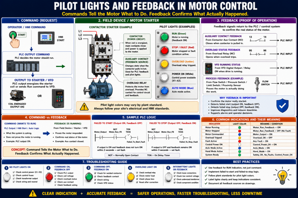
Commands tell the motor what to do. Feedback confirms what actually happened.
Pilot lights are visual indicators for operators. Feedback signals are status signals sent back to the PLC, HMI, or control system.
The motor control material identifies pilot lights as common motor control devices and lists them along with pushbuttons, selector switches, relays, contactors, overloads, and control transformers.
What Is a Pilot Light?
A pilot light is an indicator light mounted on a control panel, pushbutton station, MCC bucket, or machine enclosure.
Pilot lights are used to show status.
Common pilot light indications include:
| Pilot Light | Typical Meaning |
|---|---|
| Green | Motor running, system ready, normal condition |
| Red | Fault, stopped, overload, alarm, or unsafe condition depending on plant standard |
| Amber / Yellow | Warning, automatic mode, abnormal condition, caution |
| Blue | Special status, reset required, maintenance, or plant-specific indication |
| White | Power ON, control power available, or general status |
Important:
Pilot light color meaning can vary by plant standard. Always follow the site’s electrical and HMI standards.
A light should not just look good. It should communicate useful information.
Why Pilot Lights Matter
Pilot lights help operators and technicians quickly answer important questions:
Is the motor running?
Is the motor stopped?
Is there a fault?
Is the overload tripped?
Is control power available?
Is the machine in Auto or Hand?
Is the safety circuit healthy?
In a real plant environment, this saves time.
Instead of opening a panel immediately, the technician can first observe the operator station or HMI and understand the basic machine condition.
Basic Pilot Light Example
A simple motor starter panel may have:
Green light = Motor Running
Red light = Motor Stopped or Faulted
Amber light = Overload Trip
White light = Control Power ON
Example logic:
Motor_Run_Light = Motor_Run_Feedback

Motor_Fault_Light = Motor_Overload_Fault OR Motor_Failed_To_Start

Control_Power_Light = Control_Power_OK
This gives the operator clear visual status.
Command vs Feedback
This is one of the most important concepts in industrial motor control.
Motor Command
A motor command means the control system is requesting the motor to run.
Example:
Motor_Run_Command = ONThis may come from:
- Start pushbutton
- HOA switch in Hand
- HMI Start button
- PLC automatic sequence
- Float switch
- Pressure switch
- Timer
- VFD run command
Motor Feedback
A motor feedback signal confirms that the motor starter, VFD, or field device responded.
Example:
Motor_Run_Feedback = ONFeedback may come from:
- Contactor auxiliary contact
- VFD running status
- Motor current switch
- Pressure switch proving pump flow
- Flow switch
- Encoder
- Proximity sensor
- Limit switch movement
- Auxiliary contact from a starter
A key rule:
A PLC output ON does not prove the motor is running. Feedback proves the field response.
Why Command Alone Is Not Enough
Imagine this situation:
PLC Output = ON
Motor = Not running
Possible causes:
- Failed PLC output module
- Broken wire to starter coil
- No control voltage
- Overload tripped
- Bad contactor coil
- Bad interposing relay
- Blown fuse
- VFD fault
- Contactor mechanically stuck
- Motor disconnected
- Power circuit problem
If the PLC only looks at the output command, it may think the motor is running. But in the real world, the motor may be stopped.
That is why feedback is so important.
Common Motor Feedback Sources
1. Contactor Auxiliary Contact
A contactor auxiliary contact is one of the most common feedback methods.
When the contactor pulls in, the auxiliary contact changes state.
Example:
PLC Output energizes starter coil
        ↓
Contactor pulls in
        ↓
Auxiliary contact closes
        ↓
PLC input turns ON
        ↓
Motor_Run_Feedback = ON
The motor control textbook explains that coil and associated contact identification is used in ladder diagrams so that contacts controlled by a coil can be recognized. This is the same principle used when a contactor auxiliary contact is used for seal-in or feedback.
2. VFD Running Status
For VFD-driven motors, feedback often comes from the drive.
Common VFD feedback signals:
Drive Ready
Drive Running
Drive Faulted
At Speed
Zero Speed
Direction Status
Overload Warning
A VFD can provide feedback using:
- Digital output
- Relay output
- Ethernet/IP status
- Modbus status
- Drive network tag
3. Motor Current Feedback
A current switch or power monitor can prove that current is flowing to the motor.
This can be useful when contactor feedback is not enough.
Example:
Contactor pulled in, but no current detected
→ possible power circuit or motor issue
4. Process Feedback
Sometimes the best feedback is not electrical but process-based.
Examples:
| Motor Type | Process Feedback |
|---|---|
| Pump | Flow switch or pressure increase |
| Fan | Airflow switch or pressure differential |
| Conveyor | Proximity sensor detecting movement |
| Mixer | Speed sensor or process response |
| Door motor | Open/close limit switches |
This type of feedback confirms that the motor’s action actually affected the process.
Pilot Light vs PLC Feedback
Pilot lights and PLC feedback are related, but they are not the same thing.
| Item | Main Purpose |
|---|---|
| Pilot light | Shows status to humans |
| PLC feedback input | Shows status to the control system |
| HMI indication | Shows processed status, alarms, and diagnostics |
| Auxiliary contact | Provides electrical proof of contactor state |
| VFD status | Provides drive/motor status |
A pilot light may be wired directly from a contactor auxiliary contact, or it may be controlled by a PLC output.
Both designs exist.
Direct-Wired Pilot Light
A direct-wired pilot light may turn on when the motor starter auxiliary contact closes.
Example:
L1 ----[ M AUX ]----( Motor Run Pilot Light )---- L2Meaning:
If the contactor pulls in, the pilot light turns ON.This is simple and reliable.
PLC-Controlled Pilot Light
A PLC-controlled pilot light is energized by a PLC output.
Example:
Motor_Run_Light_Output = Motor_Run_FeedbackOr:
Motor_Fault_Light_Output = Motor_Fault_ActiveThis provides more flexibility because the PLC can decide when and how to turn on the light.
For example:
Green Light Solid = Motor Running
Green Light Flashing = Motor Starting
Red Light Solid = Fault Active
Amber Light Flashing = Warning
Basic Motor Status Logic
A good motor control system should separate these signals:
Motor_Start_Request
Motor_Run_Command
Motor_Output
Motor_Run_Feedback
Motor_Fault
Motor_Overload_OK
Simple Meaning
| Signal | Meaning |
|---|---|
| Start_Request | Operator or process is asking for motor |
| Run_Command | PLC logic decided motor should run |
| Motor_Output | PLC output to starter/VFD is ON |
| Run_Feedback | Motor starter/VFD says motor is running |
| Overload_OK | Overload relay is not tripped |
| Motor_Fault | A fault condition is active |
This structure makes troubleshooting much easier.
Example PLC Logic: Motor Run Feedback
Output Command
Motor_Output =
    Motor_Run_Command
    AND Safety_OK
    AND Overload_OK
    AND No_Faults
Feedback Monitoring
If Motor_Output is ON
AND Motor_Run_Feedback is OFF
after 3 seconds,
then Motor_Failed_To_Start_Fault = ON.
Failed to Stop Monitoring
If Motor_Output is OFF
AND Motor_Run_Feedback remains ON
after 3 seconds,
then Motor_Failed_To_Stop_Fault = ON.
This protects against conditions such as:
- Contactor did not pull in
- Auxiliary contact failed
- Contactor welded closed
- VFD did not stop
- Feedback wiring problem
- PLC input problem
Pilot Light Logic Examples
Motor Running Light
Motor_Run_Light = Motor_Run_FeedbackThis means the light is based on feedback, not only command.
Motor Commanded Light
Motor_Commanded_Light = Motor_OutputThis means the PLC is requesting the motor to run.
Fault Light
Motor_Fault_Light =
    Motor_Overload_Fault
    OR Motor_Failed_To_Start
    OR Motor_Failed_To_Stop
    OR VFD_Fault
Ready Light
Motor_Ready_Light =
    Safety_OK
    AND Overload_OK
    AND Drive_Ready
    AND No_Faults
Best Practice: Separate “Commanded” and “Running”
A common mistake is to use the PLC output as the motor running indication.
Example of weak logic:
Motor_Running_Light = Motor_OutputThis only proves the PLC output is ON.
Better logic:
Motor_Running_Light = Motor_Run_FeedbackThis proves the field device responded.
Best HMI design may show both:
Motor Commanded: ON
Motor Feedback: OFF
Fault: Failed to Start
This is very useful for troubleshooting.
HMI Status Recommendations
A good HMI motor faceplate should show:
Mode: Hand / Off / Auto
Command: ON / OFF
Output: ON / OFF
Feedback: Running / Stopped
Overload: OK / Tripped
Fault: Active / Clear
Ready: Yes / No
Runtime hours
Start count
Fault reset button
Recommended status messages:
Motor Ready
Motor Commanded
Motor Running
Motor Stopped
Motor Failed to Start
Motor Failed to Stop
Overload Tripped
VFD Faulted
Safety Circuit Not Healthy
HOA in Off
The goal is to make the HMI useful for real troubleshooting, not just decorative.
Pilot Lights on Physical Panels
Physical pilot lights are still very useful even when an HMI exists.
Examples:
Local Motor Starter Station
Green = Motor Running
Red = Motor Stopped or Faulted
Amber = Overload Trip
Pump Panel
White = Control Power ON
Green = Pump Running
Amber = Auto Mode
Red = Fault
Conveyor Panel
Green = Conveyor Running
Amber = Jam Warning
Red = E-Stop / Fault
Blue = Reset Required
Always confirm plant color standards before assigning meanings.
Feedback for Troubleshooting
Feedback helps you know where the problem is.
Case 1: Command ON, Feedback OFF
Motor_Output = ON
Motor_Run_Feedback = OFF
Possible causes:
- Coil not energizing
- Bad contactor
- Tripped overload
- No control voltage
- Broken wire
- VFD not running
- Bad feedback contact
- PLC input problem
Fault message:
Motor failed to start.Case 2: Command OFF, Feedback ON
Motor_Output = OFF
Motor_Run_Feedback = ON
Possible causes:
- Contactor welded
- Feedback contact stuck
- VFD still running
- Output bypassed
- Wiring issue
- PLC input stuck ON
Fault message:
Motor failed to stop.This condition is serious and should be investigated carefully.
Case 3: Overload Not OK
Overload_OK = OFFPossible causes:
- Overload relay tripped
- Overload contact open
- Wiring issue
- Bad input
- Motor overloaded
- Phase loss
- Mechanical jam
Fault message:
Motor overload tripped. Check load before reset.Feedback Timeout Timer
A feedback timeout timer is commonly used in PLC logic.
Example:
Motor_Output ON starts a timer.
If Motor_Run_Feedback does not turn ON before timer done,
latch Failed_To_Start fault.
Typical timer values depend on the application:
| Application | Possible Feedback Delay |
|---|---|
| Small starter motor | 1–3 seconds |
| Large motor starter | 2–5 seconds |
| VFD motor | 3–10 seconds |
| Conveyor with sensor feedback | Application dependent |
| Pump with pressure feedback | May need longer delay |
Do not use one timer value blindly for every motor. Match the timer to the machine behavior.
Flashing Pilot Lights
Flashing lights can communicate different states.
Examples:
| Light Behavior | Possible Meaning |
|---|---|
| Solid green | Running |
| Flashing green | Starting or waiting for feedback |
| Solid red | Fault active |
| Flashing red | Fault active and unacknowledged |
| Solid amber | Warning |
| Flashing amber | Auto request active but blocked |
| Flashing blue | Reset required |
Use flashing carefully. Too many flashing lights can confuse operators.
Pilot Lights and Alarm Philosophy
Pilot lights should support the alarm philosophy.
A fault light should not turn on for every minor status condition.
Example:
Status
HOA in Hand
Motor stopped
Auto request inactive
Warning
Motor current high
VFD warning active
Filter needs service
Fault
Overload tripped
Failed to start
Failed to stop
VFD fault
Safety circuit lost
Good indication helps the operator know what action to take.
Common Mistakes
Mistake 1 — Using Command as Running Feedback
A PLC output ON does not prove the motor is running.
Mistake 2 — No Failed-to-Start Logic
If the motor is commanded and feedback never appears, the system should alarm.
Mistake 3 — No Failed-to-Stop Logic
If the command is removed but feedback stays ON, the system should alarm.
Mistake 4 — Confusing Operators with Too Many Lights
Every light should have a clear purpose.
Mistake 5 — Not Showing Overload Status
Overload status is one of the most useful motor troubleshooting indications.
Industrial Pro Tips
Pro Tip 1 — Use Feedback for Running Status
Use the auxiliary contact, VFD running bit, or process feedback to confirm running.
Pro Tip 2 — Show Both Command and Feedback on HMI
This makes troubleshooting much faster.
Command ON + Feedback OFF = failed to start
Command OFF + Feedback ON = failed to stop
Pro Tip 3 — Use Meaningful Fault Text
Avoid vague messages like:
Motor FaultUse better messages:
Conveyor Motor Failed to Start
Pump Overload Tripped
Fan VFD Fault Active
Pro Tip 4 — Include Overload OK as a PLC Input
This makes diagnostics clearer.
Pro Tip 5 — Use Timers for Feedback Validation
Do not fault immediately. Allow reasonable time for the motor to respond.
Practical Field Example
A conveyor motor is started from an HMI.
The PLC turns on:
Conveyor_Motor_OutputThe contactor should pull in and close the auxiliary feedback contact:
Conveyor_Run_FBThe HMI shows:
Command: ON
Feedback: OFF
Fault: Failed to Start
This tells the technician:
The PLC wants the motor to run, but the starter feedback did not return.Next checks:
1. Check control voltage.
2. Check overload status.
3. Check PLC output module.
4. Check starter coil voltage.
5. Check contactor auxiliary contact.
6. Check feedback wiring to PLC input.
This is much better than only showing “Motor Fault.”
Quick Summary
Pilot light = visual status for operators.

Feedback = proof signal to PLC or control system.

Command = what the system wants.

Output = physical signal sent to starter or VFD.

Feedback = confirmation that the field device responded.

Running indication should usually be based on feedback, not just command.

Failed-to-start fault = output ON but feedback OFF after timeout.

Failed-to-stop fault = output OFF but feedback ON after timeout.

Good HMI status helps technicians troubleshoot faster.
Final Thoughts
Pilot lights and feedback signals are essential parts of industrial motor control. They help operators see machine status and help the PLC verify that a motor actually responded to a command.
For automation technicians, the key concept is:
Do not confuse command with feedback.
A command tells the motor to run. Feedback proves that the motor starter, VFD, or field device responded.
A strong motor control system should show clear indication for command, running feedback, overload status, faults, mode, and readiness. This improves troubleshooting, reduces downtime, and makes the system easier for operators and technicians to understand.
A motor control panel should not only control the motor. It should clearly communicate what is happening.