16. Command vs Feedback in Industrial Motor Control (16 of 22)
Why a Motor Command Does Not Prove the Motor Is Running
Introduction
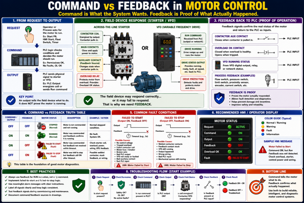
In industrial motor control, one of the most important concepts an automation technician must understand is the difference between command and feedback.
A motor can be commanded to run, but that does not always mean the motor is actually running.
A simple way to remember it is:
Command = what the system wants the motor to do.
Feedback = proof that the motor actually responded.
This concept is critical in PLC programming, HMI design, fault detection, troubleshooting, and real production environments.
A PLC output may be ON, but the motor may still be stopped because of a failed contactor coil, tripped overload, blown fuse, VFD fault, broken wire, missing phase, or mechanical problem.
That is why professional motor control systems separate request, command, output, and feedback.
What Is a Motor Command?
A motor command is the control system’s decision to run the motor.
The command may come from:
- Start pushbutton
- HMI Start button
- HOA switch in Hand
- PLC automatic sequence
- Float switch
- Pressure switch
- Timer
- VFD run command
- Production line request
Example tag names:
Motor_Start_Request
Motor_Run_Command
Motor_Output
VFD_Run_Command
Pump_Run_Command
Conveyor_Run_Command
A command means:
The system is asking the motor to run.But it does not prove that the motor actually started.
What Is Motor Feedback?
Motor feedback is a signal that confirms the motor starter, VFD, or process responded to the command.
Feedback may come from:
- Contactor auxiliary contact
- Motor starter auxiliary contact
- VFD running status
- VFD at-speed status
- Overload relay status
- Motor current switch
- Flow switch
- Pressure switch
- Encoder
- Proximity sensor
- Limit switch
- Process sensor
Example tag names:
Motor_Run_Feedback
Motor_Running_FB
DI_Motor_Run_FB
VFD_Running
Drive_At_Speed
Pump_Flow_Proven
Conveyor_Motion_FB
Feedback means:
The field device or process confirms the motor actually responded.Associated contacts are identified with the same coil/device designation in ladder diagrams, which is the same principle used when an auxiliary contact from a starter is used to indicate contactor state or provide feedback.
Command vs Feedback: Simple Example
Imagine a PLC-controlled conveyor motor.
The PLC turns ON the motor output:
Conveyor_Motor_Output = ONThe contactor should pull in.
Then the auxiliary contact should close and return feedback to the PLC:
Conveyor_Run_Feedback = ONCorrect condition:
Command ON
Feedback ON
Motor is confirmed running
Problem condition:
Command ON
Feedback OFF
Motor was commanded, but not proven running
This is where fault detection becomes important.
Command, Output, and Feedback Are Not the Same
These three signals are related, but they mean different things.
| Signal | Meaning | Example |
|---|---|---|
| Request | Someone or something asks for motor operation | Start PB, HMI Start, Auto Request |
| Command | PLC logic decides the motor should run | Motor_Run_Command |
| Output | Physical signal sent to starter or VFD | Motor_Output |
| Feedback | Proof that the field device responded | Motor_Run_Feedback |
A professional structure looks like this:
Request → Command → Output → FeedbackThis structure makes the program easier to troubleshoot and easier to explain.
Why Command Alone Is Not Enough
A motor command can be ON while the motor is not running.
Example:
Motor_Output = ON
Motor_Run_Feedback = OFF
Possible causes:
- No control voltage
- Tripped overload
- Bad contactor coil
- Failed PLC output module
- Broken wire to starter coil
- Bad interposing relay
- VFD fault
- Drive not ready
- Blown fuse
- Missing phase
- Contactor mechanically stuck
- Auxiliary feedback contact failed
- PLC feedback input failed
This is why using only the output bit as “motor running” is weak logic.
Weak logic:
Motor_Running = Motor_OutputBetter logic:
Motor_Running = Motor_Run_FeedbackBest diagnostic display:
Motor Command: ON
Motor Output: ON
Motor Feedback: OFF
Fault: Failed to Start
The Best Industrial Philosophy
A strong motor control philosophy separates each stage.
Operator / Process Request
        ↓
Permissive Check
        ↓
Motor Run Command
        ↓
Physical Output to Starter or VFD
        ↓
Motor Run Feedback
        ↓
Fault Detection
In tag form:
Motor_Start_Request
Motor_Permissives_OK
Motor_Run_Command
Motor_Output
Motor_Run_Feedback
Motor_Failed_To_Start
Motor_Failed_To_Stop
This is much better than mixing everything into one rung.
Request vs Command
A request is an intention.
Examples:
HMI_Start_PB
Local_Start_PB
Auto_Start_Request
Tank_Level_Low
Pressure_Low
A command is the PLC’s approved decision after checking conditions.
Example:
Motor_Run_Command =
    Start_Request
    AND Safety_OK
    AND Overload_OK
    AND Permissives_OK
    AND No_Faults
This distinction is important.
The operator may request the motor to start, but the PLC should only command the motor if the system is ready.
Command vs Output
A command is internal logic.
An output is the actual physical signal sent to the field device.
Example:
Motor_Run_Command = internal PLC bit
Motor_Output = PLC output to starter coil or VFD run input
The final output should normally include protection conditions:
Motor_Output =
    Motor_Run_Command
    AND Safety_OK
    AND Overload_OK
    AND No_Faults
This keeps the physical output protected.
Output vs Feedback
The output tells the field device to act.
Feedback confirms whether the field device responded.
Example:
Motor_Output = ON
Motor_Run_Feedback = ON
This usually means the starter or drive responded correctly.
But:
Motor_Output = ON
Motor_Run_Feedback = OFF
This means the PLC requested motion, but it did not receive proof.
That is a diagnostic condition.
Common Feedback Sources
1. Contactor Auxiliary Contact
A contactor auxiliary contact is one of the most common feedback signals.
When the contactor pulls in, the auxiliary contact closes.
PLC Output ON → Contactor Coil Energized → Aux Contact Closes → PLC Input ONThis confirms that the contactor changed state.
2. VFD Running Status
A VFD can provide running feedback through:
Digital output
Relay output
EtherNet/IP tag
Modbus register
Drive status word
Common VFD feedback signals include:
Drive Ready
Drive Running
Drive Faulted
Drive At Speed
Drive Direction
Zero Speed
The motor control textbook describes VFDs as devices that control AC motor speed by varying frequency and voltage, which makes drive status feedback useful for confirming actual motor/drive state.
3. Overload Status
An overload relay can provide a healthy or tripped signal.
Example:
Overload_OK = ONmeans the overload contact is healthy.
Overload_OK = OFFmeans the overload tripped or the circuit is open.
The motor control glossary defines overload protection as a device or system that prevents a motor from drawing too much current, overheating, and burning out.
4. Process Feedback
Sometimes the best proof is not electrical feedback but process feedback.
Examples:
| Motor Type | Better Feedback |
|---|---|
| Pump | Flow switch or pressure increase |
| Fan | Airflow switch or differential pressure |
| Conveyor | Motion sensor or product movement |
| Door motor | Open/close limit switch |
| Mixer | Speed sensor or process response |
A pump contactor may be ON, but if there is no flow, the process may still have a problem.
Failed to Start Fault
A failed to start fault happens when the motor is commanded to run, but feedback does not turn ON within a set time.
Example logic:
If Motor_Output is ON
AND Motor_Run_Feedback is OFF
for 3 seconds
THEN Motor_Failed_To_Start = ON
This detects problems such as:
- Contactor did not pull in
- VFD did not start
- Overload tripped
- Broken output wire
- No control voltage
- Bad coil
- Bad auxiliary contact
- PLC input issue
Example HMI Message
Motor Failed to Start — Command ON but Run Feedback was not detected.This is much better than a generic “Motor Fault” message.
Failed to Stop Fault
A failed to stop fault happens when the motor command is OFF, but feedback remains ON after a timeout.
Example logic:
If Motor_Output is OFF
AND Motor_Run_Feedback is ON
for 3 seconds
THEN Motor_Failed_To_Stop = ON
Possible causes:
- Welded contactor
- Feedback contact stuck
- VFD still running
- Output bypassed
- Wrong wiring
- PLC input stuck ON
- Mechanical system still moving
This condition can be serious because it may indicate the motor is running when the control system believes it should be stopped.
Example HMI Message
Motor Failed to Stop — Run Feedback remained ON after the command was removed.Command and Feedback Truth Table
| Command / Output | Feedback | Meaning |
|---|---|---|
| OFF | OFF | Normal stopped condition |
| ON | ON | Normal running condition |
| ON | OFF | Failed to start or feedback missing |
| OFF | ON | Failed to stop, welded contactor, or stuck feedback |
This table is simple but powerful.
It helps operators and technicians understand the motor state quickly.
Feedback Timeout Timers
Feedback should usually be checked with a timer.
Do not fault immediately the instant the output turns ON. Give the device time to respond.
Example delay times:
| Equipment | Possible Delay |
|---|---|
| Small contactor motor | 1–3 seconds |
| Large starter | 2–5 seconds |
| VFD start | 3–10 seconds |
| Pump pressure proof | Application dependent |
| Conveyor motion proof | Application dependent |
Use a delay that makes sense for the machine.
PLC Logic Example
Inputs
DI_Start_PB
DI_Stop_OK
DI_Safety_OK
DI_Overload_OK
DI_Motor_Run_FB
Internal Bits
Motor_Start_Request
Motor_Run_Command
Motor_Output
Motor_Failed_To_Start
Motor_Failed_To_Stop
Start Request
Motor_Start_Request = DI_Start_PBRun Command
Motor_Run_Command =
    Motor_Start_Request
    AND DI_Stop_OK
    AND DI_Safety_OK
    AND DI_Overload_OK
    AND NOT Motor_Failed_To_Start
    AND NOT Motor_Failed_To_Stop
Final Output
Motor_Output =
    Motor_Run_Command
    AND DI_Safety_OK
    AND DI_Overload_OK
Failed to Start
If Motor_Output = ON
AND DI_Motor_Run_FB = OFF
after timeout
then Motor_Failed_To_Start = ON
Failed to Stop
If Motor_Output = OFF
AND DI_Motor_Run_FB = ON
after timeout
then Motor_Failed_To_Stop = ON
HMI Design: Show Both Command and Feedback
A good HMI should show both command and feedback.
Recommended motor faceplate indicators:
Mode: Hand / Off / Auto
Request: Active / Inactive
Command: ON / OFF
Output: ON / OFF
Feedback: Running / Stopped
Overload: OK / Tripped
Fault: Active / Clear
Good HMI examples:
Command ON + Feedback ON = Running
Command ON + Feedback OFF = Failed to Start
Command OFF + Feedback ON = Failed to Stop
Overload Not OK = Overload Trip
This makes troubleshooting faster.
Pilot Lights: Which Signal Should Drive the Light?
A common question:
Should the green running light be based on the command or the feedback?
Best practice:
Running Light = Motor_Run_FeedbackWhy?
Because feedback proves the starter or drive actually responded.
A separate “Commanded” indication can also be useful:
Commanded Light = Motor_OutputThis allows the operator or technician to see both:
The PLC is asking for the motor.
The motor is actually proven running.
Troubleshooting Examples
Example 1 — Command ON, Feedback OFF
Condition:
Motor_Output = ON
Motor_Run_Feedback = OFF
Troubleshooting path:
1. Check control voltage.
2. Check PLC output.
3. Check interposing relay.
4. Check contactor coil voltage.
5. Check overload status.
6. Check VFD ready/fault status.
7. Check auxiliary contact.
8. Check feedback wire to PLC input.
Possible HMI message:
Motor Failed to Start — Check starter coil, overload, VFD, and feedback.Example 2 — Command OFF, Feedback ON
Condition:
Motor_Output = OFF
Motor_Run_Feedback = ON
Troubleshooting path:
1. Verify motor is actually stopped.
2. Check for welded contactor.
3. Check VFD status.
4. Check auxiliary contact stuck closed.
5. Check PLC input wiring.
6. Check if output is bypassed.
Possible HMI message:
Motor Failed to Stop — Feedback remained ON after output turned OFF.Example 3 — Feedback Flickering
Condition:
Motor_Run_Feedback flickers ON/OFFPossible causes:
- Loose auxiliary contact
- Loose terminal
- Chattering contactor
- Low control voltage
- Bad PLC input
- Vibration
- Weak relay
- Feedback debounce needed
Possible correction:
Check wiring and device first.
Use debounce only after confirming the signal source is healthy.
Command vs Feedback in VFD Systems
With VFD systems, command and feedback are especially important.
A PLC may send:
VFD_Run_Command = ONBut the drive may not run because:
- Drive is faulted
- Drive is not ready
- Enable input is missing
- Safe torque off is active
- Speed reference is zero
- Network command source is wrong
- Motor parameters are incorrect
- Drive is in local mode
- Interlock is open
Useful VFD feedback bits:
VFD_Ready
VFD_Running
VFD_At_Speed
VFD_Faulted
VFD_Remote_Mode
VFD_STO_OK
Better logic:
Motor_Running = VFD_Running AND NOT VFD_FaultedFor speed-controlled applications, At Speed may also be important:
Motor_At_Speed = VFD_At_SpeedCommand vs Feedback in Process Systems
Sometimes motor run feedback is not enough.
Example: Pump system.
The motor may be running, but the pump may not be moving fluid.
Possible causes:
- Closed valve
- Air locked pump
- Broken coupling
- Pump cavitation
- Blocked suction line
- Impeller issue
In that case, better feedback is:
Pump_Run_Feedback = VFD_Running
Pump_Process_Feedback = Flow_Proven OR Pressure_Proven
Fault logic:
If Pump_Run_Feedback = ON
AND Flow_Proven = OFF
after delay
then Pump_No_Flow_Fault = ON
This is a more advanced and more industrial way to think.
Common Mistakes
Mistake 1 — Using Output as Running Status
Motor_Running = Motor_OutputThis does not prove the motor is running.
Mistake 2 — No Feedback Timeout
If feedback never arrives, the system should detect it.
Mistake 3 — No Failed-to-Stop Detection
A welded contactor or stuck feedback can be dangerous.
Mistake 4 — Not Showing Command and Feedback Separately
If the HMI only says “Running,” troubleshooting becomes harder.
Mistake 5 — Ignoring Process Feedback
For pumps, fans, conveyors, and mixers, electrical feedback may not prove the process is actually working.
Industrial Pro Tips
Pro Tip 1 — Use Clear Tag Names
Good names:
Motor_Run_Command
Motor_Output
Motor_Run_FB
Motor_OL_OK
Motor_Failed_To_Start
Motor_Failed_To_Stop
Avoid unclear names like:
Motor_On
Motor_Status
Motor_Bit
Pro Tip 2 — Build a Motor Faceplate
A good motor faceplate should show:
Request
Command
Output
Feedback
Overload
Fault
Mode
Reset
This makes troubleshooting much faster.
Pro Tip 3 — Use Feedback Timers
Do not create instant faults. Use a reasonable timer based on how the device behaves.
Pro Tip 4 — Alarm With Meaning
Weak alarm:
Motor FaultBetter alarm:
Conveyor Motor Failed to Start — Command ON, feedback OFF.Best alarm:
Conveyor Motor Failed to Start — Check overload, starter coil, VFD ready status, and feedback input.Pro Tip 5 — Treat Feedback Mismatch Seriously
A command/feedback mismatch means the PLC’s expectation does not match the field.
That is exactly what troubleshooting is about.
Quick Summary
Command = what the control system wants.

Output = physical signal sent to the starter or VFD.

Feedback = proof that the field device responded.

Command ON + Feedback ON = normal running.

Command ON + Feedback OFF = failed to start.

Command OFF + Feedback ON = failed to stop or stuck feedback.

Running indication should usually be based on feedback, not output.

Good HMI design shows command, output, feedback, overload, and fault state.

Feedback makes troubleshooting faster and safer.
Final Thoughts
Command vs feedback is one of the most important ideas in industrial motor control.
A PLC output does not prove a motor is running. It only proves the PLC is trying to run it. Feedback proves that the starter, VFD, or process responded.
For automation technicians, this concept is extremely useful in real troubleshooting. When a motor does not start, do not guess. Check the request, command, output, feedback, overload status, control voltage, and field device.
A professional control system does not just command a motor. It verifies that the motor responded and provides meaningful diagnostics when it does not.
That is the difference between basic motor control and industrial motor control.