7. Overload Protection in Industrial Motor Control (7 of 22)
Protecting Motors from Excessive Current and Overheating
Introduction
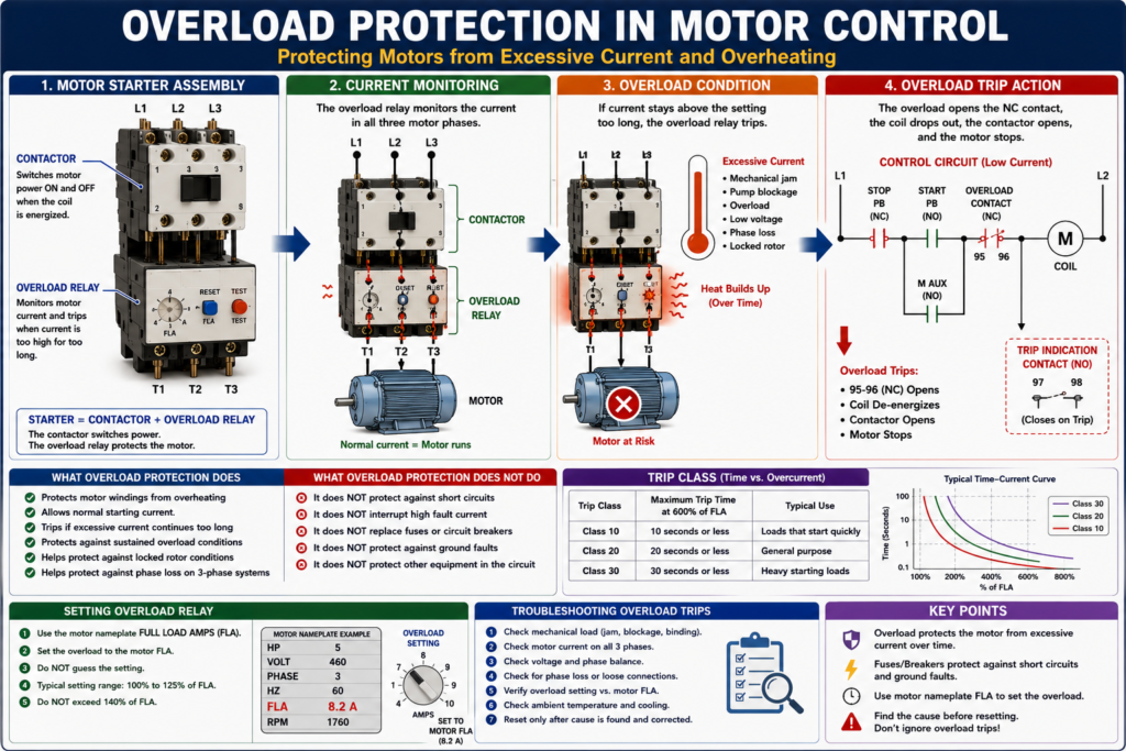
Overload protection is one of the most important parts of an industrial motor control system. A motor can be connected correctly, the contactor can pull in, and the PLC output can be ON, but if the motor is overloaded for too long, it can overheat and fail.
That is why motor starters commonly include an overload relay.
A simple way to understand overload protection is:
The overload relay protects the motor from excessive current over time.
It is important to understand that overload protection is different from short-circuit protection. A fuse or circuit breaker protects against very high fault current. An overload relay protects the motor from overheating due to sustained excessive current.
Defines overload protection as a device or system that prevents a motor from drawing too much current, overheating, and burning out. It also defines an overload relay as a relay that responds to electrical overloads at a preset value.
What Is an Overload?
An overload happens when a motor is required to do more work than it is designed to handle.
Defines overload as the application of excessive load to a motor.
In real industrial equipment, overloads can happen because of:
- Conveyor jam
- Pump blockage
- Bearing failure
- Gearbox issue
- Product buildup
- Mechanical binding
- Low voltage
- Phase loss
- Incorrect motor wiring
- Incorrect overload setting
- Motor undersized for the load
- Locked rotor condition
When the motor load increases, the motor current increases. If the condition continues, the motor windings heat up. If the heat becomes too high, the insulation can be damaged and the motor can fail.
What Is an Overload Relay?
An overload relay is a protective device used with a motor starter. Its job is to detect when the motor is drawing too much current for too long.
The overload relay is usually mounted below the contactor in a motor starter assembly.
A basic motor starter is:
Contactor + Overload Relay = Motor StarterThe contactor switches power to the motor.
The overload relay protects the motor from excessive current over time.
The motor control textbook explains that the basic difference between a contactor and a motor starter is the addition of overload relays. It also explains that overload protection protects motor windings from excessive heat caused by motor overloading.
What Overload Protection Does
Overload protection is designed to:
- Protect motor windings from overheating
- Allow normal motor starting current
- Trip if excessive current continues too long
- Protect against sustained overload conditions
- Help protect against locked rotor conditions
- Help protect against phase loss on three-phase systems
- Open the control circuit and stop the motor
Overload relays allow harmless temporary overloads, such as motor starting, without interrupting the circuit, but will trip if current is high enough to damage the motor over time.
What Overload Protection Does Not Do
This is very important:
An overload relay is not a short-circuit protection device.
Overload relays are not designed to interrupt high fault current like a fuse or circuit breaker.
| Device | Protects Against | Typical Behavior |
|---|---|---|
| Fuse / Circuit Breaker | Short circuit and ground fault | Fast trip during high fault current |
| Overload Relay | Excessive motor current over time | Time-based trip |
| Contactor | Switching motor power | Opens/closes based on coil |
| PLC | Logic and monitoring | Does not replace electrical protection |
Overload protection is not designed to break, or may not be capable of breaking, short-circuit current or ground-fault current. Short-circuit and ground-fault protection is handled by branch and feeder breakers or fuses.
Why Motors Need Special Protection
Motors are different from many other electrical loads because they draw a large amount of current when starting.
This startup current is called inrush current.
Inrush current is the amount of current drawn when a motor is first switched on and can be 6 to 8 times the normal running current.
Because of this, motor protection must be able to do two things:
- Allow the motor to start normally
- Trip if the overload condition lasts too long
If overload protection tripped instantly every time current increased, the motor would trip every time it started. That is why overload relays have a time delay behavior.
Basic Overload Relay Operation
A typical overload relay monitors current through the motor phases.
If current stays too high for too long, the overload trips.
When it trips, a normally closed overload contact opens in the control circuit.
Example control circuit:
L1 ----[/ STOP]----[ START ]----[/ OL ]----( M )
              |----[ M AUX ]----|
L2
When the overload is healthy:
OL contact closed → M coil can energizeWhen the overload trips:
OL contact opens → M coil drops out → Contactor opens → Motor stopsThis is one of the most important concepts:
The overload relay monitors the power circuit, but it usually stops the motor by opening the control circuit.
Power Section vs Control Contact
An overload relay has two important parts:
1. Power Section
The power section carries or monitors the motor current.
It is connected between the contactor and the motor:
Contactor → Overload Relay → Motor2. Control Contact
The control contact is usually a normally closed contact wired in series with the contactor coil.
Common terminal numbers are often:
95 - 96 = Normally closed overload trip contact
97 - 98 = Normally open overload trip indication contact
When the overload trips:
- 95–96 opens
- 97–98 closes, if available
This allows the control system to stop the motor and optionally report an overload trip to the PLC or pilot light.
Types of Overload Relays
1. Thermal Overload Relay
A thermal overload relay responds to heat caused by current flow.
Common thermal overload designs include:
- Bimetallic overload relay
- Heater element overload relay
- Melting alloy / eutectic alloy overload relay
Defines a heater coil as a sensing device that monitors heat generated by excessive current and ambient temperature changes. It also defines a bimetallic strip as two dissimilar metals that perform the tripping action in a bimetallic overload relay.
2. Electronic Overload Relay
An electronic overload relay uses electronic sensing to monitor current.
Common features may include:
- Adjustable current setting
- Phase loss detection
- Ground fault indication on some models
- Trip class selection
- Remote reset on some models
- Communication to PLC or network on advanced models
Electronic overloads are common in modern industrial panels because they provide more diagnostic information than basic thermal overloads.
Trip Class Explained
Trip class tells how quickly an overload relay trips under a defined overload condition.
The glossary defines trip class as the maximum time in seconds at which the overload relay will trip when current is at 600% of its rating. For example, a Class 20 relay trips in 20 seconds or less.
Common trip classes include:
| Trip Class | Meaning |
|---|---|
| Class 10 | Trips faster |
| Class 20 | Medium trip time |
| Class 30 | Slower trip time |
Overload relays are rated by trip class, with common classes including 10, 20, and 30. A Class 10 overload relay must trip the motor offline in 10 seconds or less at 600% of full-load amperes.
A higher trip class may be used for motors that need more time to accelerate, but it must still be selected correctly for the motor and application.
Full Load Amps and Overload Setting
The motor overload setting should be based on the motor nameplate Full Load Amps, commonly called FLA.
Defines full load current as the current required by the motor to produce full-load torque at rated speed.
Motor nameplate FLA, not just generic tables, is used for sizing overloads for the motor.
This is why checking the motor nameplate is so important.
Example nameplate:
Motor: 3 HP
Voltage: 460 VAC
FLA: 4.8 A
Phase: 3
Hz: 60
RPM: 1760
The overload relay should be set according to the motor nameplate FLA and the applicable design/standard requirements.
Practical field rule:
Never guess the overload setting. Always verify the motor nameplate FLA.
Locked Rotor Condition
A locked rotor condition occurs when the motor rotor cannot turn even though power is applied.
This can happen because of:
- Mechanical jam
- Seized bearing
- Locked pump
- Blocked conveyor
- Gearbox failure
- Product jam
- Motor internal failure
Defines locked rotor as a condition where the motor is so overloaded that the rotor cannot turn, regardless of how much current it draws. It also states that locked rotor amps can be high enough to damage insulation and burn up the motor.
A locked rotor is serious because current can become very high and heat can build quickly.
Phase Loss and Overload Protection
On a three-phase motor, losing one phase can cause the motor to draw abnormal current and overheat.
This is called single phasing or phase loss.
Symptoms may include:
- Motor hums
- Motor will not start
- Motor runs hot
- Overload trips
- Reduced torque
- Higher current on remaining phases
- VFD or starter fault
Overload protection also guards against failure of a motor to start from a locked rotor and loss of a phase on a three-phase system.
When an overload trips, always check for phase loss, not just mechanical overload.
Why You Should Not Keep Resetting an Overload
An overload trip is not just a nuisance. It is a warning.
Repeatedly resetting an overload without finding the cause can damage the motor or create a safety hazard.
Before resetting, ask:
- Why did it trip?
- Was the motor overloaded?
- Is the load jammed?
- Is there phase loss?
- Is the overload setting correct?
- Is the motor FLA correct?
- Is the motor hot?
- Is the motor starting too frequently?
- Is voltage low?
- Is there a mechanical problem?
Practical rule:
Reset once only after checking the cause. Do not repeatedly reset an overload as a “fix.”
Common Causes of Overload Trips
| Cause | What to Check |
|---|---|
| Conveyor jam | Product buildup, belt tension, rollers |
| Pump blockage | Suction/discharge restriction, impeller |
| Bearing failure | Noise, heat, vibration |
| Low voltage | Measure voltage under load |
| Phase loss | Check all three phases |
| Wrong overload setting | Compare with motor nameplate FLA |
| Frequent starts | Check start/stop cycling |
| Mechanical binding | Disconnect load if safe and approved |
| Motor undersized | Compare motor HP to application |
| Ambient heat | Panel temperature, motor cooling |
| Cooling fan blocked | Motor fan cover, airflow |
Troubleshooting an Overload Trip
Use a structured method.
Step 1 — Safety First
Before touching equipment, follow plant safety procedures and LOTO requirements.
Do not assume a tripped overload means the circuit is safe. Line voltage may still be present upstream.
Step 2 — Identify Which Overload Tripped
If there are multiple starters in the panel, identify the correct motor starter.
Look for:
- Red trip indicator
- Overload reset button position
- PLC alarm
- HMI fault
- Motor tag number
- Panel drawing reference
Step 3 — Check the Motor Nameplate
Record:
Voltage
FLA
HP
Phase
RPM
Service Factor
Duty
Compare the overload setting to the motor FLA.
Step 4 — Inspect the Mechanical Load
Look for:
- Jammed conveyor
- Locked pump
- Stuck fan
- Product buildup
- Gearbox issue
- Shaft coupling issue
- Bearing failure
- Abnormal noise or smell
Step 5 — Check Voltage and Phase Balance
Measure line voltage safely and according to your site procedures.
Check:
L1-L2
L2-L3
L1-L3
Verify all phases are present and reasonably balanced.
Step 6 — Check Motor Current
Use a clamp meter if approved and safe.
Check current on all three phases:
T1
T2
T3
Compare to motor FLA.
If current is high on all phases, suspect overload or mechanical load.
If one phase is missing or current is unbalanced, suspect phase loss, bad contactor contact, fuse, wiring, or motor winding issue.
Step 7 — Check the Contactor and Overload Connections
Look for:
- Loose terminals
- Burned wires
- Heat discoloration
- Damaged overload
- Pitted contactor contacts
- One phase not passing through
- Incorrect wire size
- Poor connection at motor starter
Step 8 — Reset Only When Cause Is Understood
After checking the cause and confirming it is safe, reset the overload according to site procedure.
Some overload relays require a cooling period before reset.
Overload Contact in PLC Logic
In modern systems, the overload status is often wired to the PLC.
Example tags:
DI_Motor_OL_OK
Motor_Overload_Fault
Motor_Run_Command
Motor_Run_Feedback
Typical logic:
Motor_OL_OK = overload contact is closed

If Motor_OL_OK is false,
then latch Motor_Overload_Fault.
Motor output logic:
Motor_Output =
    Motor_Run_Command
    AND Motor_OL_OK
    AND Safety_OK
    AND No_Faults
Fault reset logic:
If Reset_PB
AND Motor_OL_OK
AND Safety_OK
then unlatch Motor_Overload_Fault.
Important:
Do not allow a PLC reset button to hide a real overload condition. The physical overload must be healthy before the fault can clear.
Overload Trip vs Motor Failed to Start
These two faults are related but different.
| Condition | Meaning |
|---|---|
| Overload Trip | Overload relay detected excessive current over time |
| Failed to Start | Motor was commanded but feedback did not turn ON |
| Phase Loss | One phase missing or abnormal |
| Locked Rotor | Motor cannot turn under power |
| Jam Fault | Process/mechanical condition prevents motion |
Example logic:
If Motor_Output = ON
and Motor_Run_Feedback = OFF
after 3 seconds,
then Motor_Failed_To_Start_Fault = ON.
But if the overload contact opens:
Motor_Overload_Fault = ON
Motor_Output = OFF
This makes troubleshooting clearer for the operator and technician.
HMI Indications for Overload Protection
A good HMI should not just say “Motor Fault.”
It should give meaningful status.
Recommended HMI messages:
Motor Overload Tripped
Check mechanical load before reset
Verify overload relay and motor FLA setting
Check for phase loss or jam condition
Recommended motor status indicators:
| HMI Indicator | Meaning |
|---|---|
| Motor Commanded | PLC is requesting motor ON |
| Motor Running Feedback | Motor/starter feedback is ON |
| Overload Healthy | Overload contact is closed |
| Overload Tripped | Overload contact opened |
| Failed to Start | Command ON but no feedback |
| Fault Reset Required | Fault is latched until reset |
Practical Field Example
A conveyor motor trips overload during production.
Do not only reset it.
Use this approach:
- Verify the correct motor starter.
- Check HMI alarm and PLC status.
- Inspect conveyor for product jam.
- Check belt tension and rollers.
- Check motor temperature.
- Verify overload setting against motor FLA.
- Check voltage on all three phases.
- Check current on each phase during restart.
- Confirm run feedback returns to PLC.
- Monitor for repeat trip.
This method helps you find the real cause instead of just clearing the symptom.
Industrial Pro Tips
Pro Tip 1 — Overload Trip Is a Symptom
An overload trip tells you the motor was in trouble. Find out why.
Pro Tip 2 — Check the Mechanical Load First
Many electrical overload trips are caused by mechanical problems.
Pro Tip 3 — Compare Current to Nameplate FLA
Do not guess. Measure current and compare it to the motor nameplate.
Pro Tip 4 — Check All Three Phases
A missing phase can make a motor overheat quickly.
Pro Tip 5 — Do Not Bypass the Overload
Bypassing an overload relay removes motor protection and can destroy the motor or create a hazard.
Common Mistakes
Mistake 1 — Resetting Repeatedly
Repeated resets without troubleshooting can burn the motor.
Mistake 2 — Setting the Overload Too High
This may prevent nuisance trips, but it can also allow the motor to overheat.
Mistake 3 — Confusing Breaker Trip with Overload Trip
A breaker trip and an overload trip usually point to different types of problems.
Mistake 4 — Ignoring Phase Loss
If one fuse is blown or one contactor pole is bad, the motor may single-phase and trip overload.
Mistake 5 — Not Checking the Load
The motor may be fine. The driven equipment may be the real problem.
Quick Summary
Overload relay = protects motor from excessive current over time.

Fuse/breaker = protects against short circuit and ground fault.

Contactor = switches motor power.

PLC = commands and monitors, but does not replace motor protection.
Final Thoughts
Overload protection is essential in industrial motor control. It protects the motor from excessive current, overheating, locked rotor conditions, phase loss, and sustained mechanical overloads.
A good technician understands that an overload relay is not the same as a fuse or breaker. The overload relay protects the motor over time, while fuses and breakers protect against short circuits and high fault current.
When an overload trips, do not just reset it. Treat it as a troubleshooting clue. Check the mechanical load, motor current, voltage, phase balance, overload setting, and motor nameplate data.
The goal is not only to restart the motor. The goal is to understand why it tripped and prevent repeat failures.