8. Motor Nameplate Explained for Automation Technicians (8 of 22)
How Automation Technicians Read Motor Data in the Field
Introduction
A motor nameplate is one of the most important sources of information on an electric motor. Before replacing a motor, setting an overload relay, configuring a VFD, checking current draw, or troubleshooting a motor fault, the nameplate should be verified.
The motor nameplate tells you how the motor was designed to operate.
It usually includes information such as:
- Voltage
- Full-load amps
- Horsepower
- Phase
- Frequency
- RPM
- Service factor
- Frame size
- Duty rating
- Enclosure type
- Wiring connection diagram
- Code letter
- Insulation class
- Efficiency
A simple way to think about it:
The motor nameplate is the motor’s electrical ID card.
The motor nameplate contains important information about the connection and use of the motor, and that common nameplate information helps make motors more interchangeable among manufacturers.
Why the Motor Nameplate Matters
The motor nameplate is not just a label. It directly affects field decisions.
You use the nameplate to:
- Set the overload relay
- Configure VFD motor parameters
- Verify correct voltage connection
- Confirm horsepower rating
- Check motor full-load current
- Verify phase and frequency
- Identify frame size for replacement
- Confirm duty cycle
- Confirm if the motor is suitable for the application
- Compare actual measured current to rated current
A technician should not guess these values. Guessing can damage equipment or create unsafe conditions.
Before changing settings, always read the nameplate.
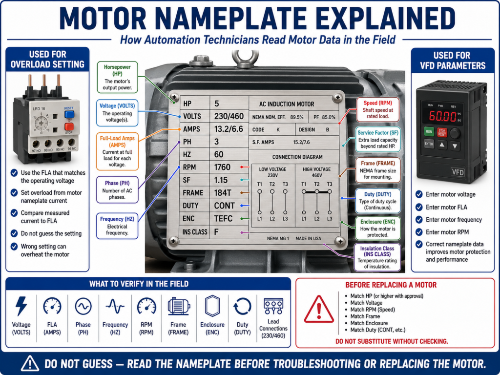
Basic Example of a Motor Nameplate
A typical industrial motor nameplate may show something like this:
HP: 5
VOLTS: 230/460
AMPS: 13.2/6.6
PHASE: 3
HZ: 60
RPM: 1760
SF: 1.15
FRAME: 184T
DUTY: CONT
INS CLASS: F
ENCLOSURE: TEFC
At first, this can look like a lot of information. But each value tells you something important about how the motor should be powered, protected, installed, and controlled.
1. Voltage Rating
The voltage rating tells you what supply voltage the motor is designed to operate on.
Common industrial motor voltages include:
208 VAC
230 VAC
460 VAC
575 VAC
Some motors are dual-voltage motors. For example:
230/460 VACThis means the motor can be connected for either 230 V or 460 V, depending on how the leads are wired.
Voltage rating is abbreviated as V on the nameplate and indicates the voltage at which the motor is designed to operate. It also notes that NEMA requires a motor to carry rated horsepower at nameplate voltage ±10%, though not necessarily at rated temperature rise.
Practical Technician Note
If a motor is wired for the wrong voltage, it can:
- Draw excessive current
- Fail to start
- Run hot
- Trip overload
- Produce low torque
- Burn windings
Always confirm the motor lead connection diagram before energizing a dual-voltage motor.
2. Full-Load Amps
Full-load amps, often shown as FLA, A, or AMPS, is one of the most important values on the nameplate.
It tells you how much current the motor should draw when operating at rated load, rated voltage, and rated frequency.
Defines nameplate current rating as full-load current at rated load, rated voltage, and rated frequency. It also explains that a motor not fully loaded draws less than the nameplate current, while an overloaded motor draws more than the rated nameplate current.
Example:
VOLTS: 230/460
AMPS: 13.2/6.6
This means:
- At 230 V, the motor full-load current is 13.2 A.
- At 460 V, the motor full-load current is 6.6 A.
Why FLA Is Important
FLA is used for:
- Setting overload relays
- Configuring VFD motor current
- Comparing measured current
- Troubleshooting overload trips
- Verifying motor loading
Practical rule:
If the motor is running above nameplate FLA, investigate the load, voltage, phase balance, and motor condition.
3. Horsepower Rating
Horsepower, shown as HP, tells you the mechanical output power the motor shaft can produce.
The HP rating is a measure of the full-load output power the motor shaft can produce without reducing the motor’s operating life.
Common examples:
1 HP
3 HP
5 HP
10 HP
25 HP
Horsepower is important when replacing a motor because the replacement must be properly sized for the mechanical load.
Practical Technician Note
Do not replace a failed motor with a different horsepower motor unless engineering or the correct procedure approves it.
Too small:
- Motor overloads
- Trips overload
- Runs hot
- Fails early
Too large:
- May create mechanical stress
- May affect protection sizing
- May require different starter/VFD sizing
- May not match the application design
4. Phase Rating
The phase rating tells you whether the motor is:
Single-phase
Three-phase
DC
Phase rating is abbreviated as PH and may be listed as DC, single-phase AC, or three-phase AC.
Most industrial motors are three-phase because three-phase motors are efficient, reliable, and well suited for industrial loads.
Example:
PH: 3This means the motor requires three-phase power.
Practical Technician Note
Never assume the motor is three-phase just because it is in an industrial panel. Always verify the nameplate and wiring.
5. Frequency Rating
Frequency is shown as Hz.
Common values:
60 Hz
50 Hz
In the United States, 60 Hz is standard. In many other countries, 50 Hz is common.
Line frequency may be abbreviated as CY, CYC, or Hz, and that hertz means cycles per second.
Frequency matters because AC motor speed is related to frequency.
If you operate a motor at the wrong frequency, the motor speed, torque, current, and heating can be affected.
6. RPM / Motor Speed
RPM means revolutions per minute.
Example:
RPM: 1760This tells you the approximate speed of the motor shaft when the motor is delivering rated horsepower.
Rated motor speed is not the exact operating speed, but the approximate speed at which the motor rotates while delivering rated horsepower to a load. It also states that AC motor speed is determined by the number of poles and the frequency of the supply voltage.
Common induction motor speeds at 60 Hz are near:
3600 RPM
1800 RPM
1200 RPM
900 RPM
A motor nameplate may show slightly lower actual speed, such as 1760 RPM instead of 1800 RPM, because of slip.
Practical Technician Note
If the nameplate shows 1760 RPM, do not expect exactly 1800 RPM under load. That difference is normal for induction motors.
7. Service Factor
Service factor is usually shown as SF.
Example:
SF: 1.15Service factor is a multiplier applied to the motor’s normal horsepower rating to indicate increased output or overload capacity under certain conditions. Common values include 1.0, 1.15, and 1.25; if no service factor is listed, 1.00 is assumed.
Example:
10 HP motor with SF 1.15This means the motor may be capable of handling occasional load above 10 HP under specified conditions.
Important Note
Service factor is not a normal operating target.
Do not use service factor as an excuse to overload the motor continuously.
Practical rule:
Operate the motor at or below rated load whenever possible. Treat service factor as margin, not normal operation.
8. Duty Rating
Duty tells you how long the motor is designed to operate under load.
Common examples:
CONT = Continuous duty
INTER = Intermittent duty
Motors are classified as continuous duty or intermittent duty. Continuous-duty motors are rated to operate continuously without damage or reduction in motor life, while intermittent-duty motors operate for short periods and must cool before restarting.
Practical Technician Note
If a motor is rated intermittent duty and it is being used continuously, it may overheat and fail.
Always verify duty rating when replacing or applying a motor.
9. Frame Size
Frame size tells you the physical mounting dimensions of the motor.
Example:
FRAME: 184TFrame size affects:
- Mounting bolt pattern
- Shaft height
- Shaft diameter
- Motor length
- Replacement compatibility
Frame size refers to physical dimensions established by NEMA and IEC, including physical size, construction, dimensions, and other physical characteristics.
Practical Technician Note
Two motors can have the same horsepower and voltage but different frame sizes. If the frame does not match, the motor may not physically fit the machine.
10. Enclosure Type
The enclosure tells you how the motor is protected from the surrounding environment.
Common examples:
ODP  = Open Drip Proof
TEFC = Totally Enclosed Fan Cooled
TENV = Totally Enclosed Non-Ventilated
Explosion-proof
Washdown duty
Motor enclosure selection depends on ambient temperature and surrounding conditions, and that open and totally enclosed are two general classifications.
Practical Technician Note
Use the correct motor enclosure for the environment.
For example:
- Wet area → washdown or sealed motor may be required
- Dusty area → totally enclosed motor may be preferred
- Hazardous area → properly rated hazardous-location motor may be required
Do not replace a special enclosure motor with a general-purpose motor unless approved.
11. Code Letter
The code letter gives information about locked-rotor current.
When AC motors start at full voltage, they draw inrush or locked-rotor current much greater than their full-load running current. The code letter identifies the locked-rotor rating in kVA per horsepower and helps determine breaker and fuse sizing.
Example:
CODE: GThis is more often used in design and protection sizing, but it is still useful information for troubleshooting and replacement.
12. Connection Diagram
Some motors include a connection diagram on the nameplate, inside the conduit box, or on a connection plate.
Connection diagrams may be found on the motor nameplate, inside the motor conduit box, or on a special connection plate, and that they indicate specific connections for dual-voltage motors.
This is extremely important for motors with multiple leads.
Example:
Low Voltage: connect leads in parallel
High Voltage: connect leads in series
For a dual-voltage motor, the connection must match the supply voltage.
Practical Technician Note
Before energizing a replacement motor:
1. Verify supply voltage.
2. Verify motor nameplate voltage.
3. Verify motor lead connection diagram.
4. Verify overload setting.
5. Verify rotation direction.
Motor Nameplate and VFD Setup
When configuring a VFD, the motor nameplate is critical.
Common VFD parameters taken from the nameplate include:
Motor Voltage
Motor FLA
Motor Frequency
Motor RPM
Motor HP or kW
Motor Poles / Speed Data
If these values are entered incorrectly, the VFD may:
- Trip overload
- Run motor incorrectly
- Provide poor torque
- Fail autotune
- Display wrong speed/current
- Fail to protect the motor properly
Practical VFD rule:
The VFD protects and controls the motor based on the data you enter. Bad nameplate data creates bad drive behavior.
Motor Nameplate and Overload Relay Setting
The overload relay setting should be based on the motor nameplate current.
Example:
Nameplate:
VOLTS: 460
AMPS: 6.6
If operating at 460 V, the overload must be set based on the 6.6 A rating, not the 13.2 A rating for 230 V.
This mistake is common on dual-voltage motors.
Practical rule:
Use the FLA that matches the actual operating voltage.
Nameplate Troubleshooting Examples
Example 1 — Motor Trips Overload
Nameplate:
FLA: 6.6 AMeasured current:
L1: 8.4 A
L2: 8.2 A
L3: 8.5 A
Interpretation:
The motor is drawing above rated current on all phases. Check for mechanical overload, low voltage, incorrect application, blocked pump, conveyor jam, or wrong overload setting.
Example 2 — Wrong Voltage Connection
Nameplate:
230/460 V
13.2/6.6 A
Supply:
460 VIf motor leads are connected for 230 V, the motor can be damaged.
Always verify lead connections.
Example 3 — Wrong Replacement Motor
Original motor:
5 HP
460 V
1760 RPM
184T Frame
TEFC
Continuous Duty
Replacement motor:
5 HP
460 V
3450 RPM
Different frame
ODP enclosure
Even though the horsepower and voltage match, this is likely not a correct replacement. RPM, frame, enclosure, and duty also matter.
Practical Field Checklist
Before replacing or configuring a motor, record:
Motor Tag:
Manufacturer:
Model/Catalog Number:
HP:
Voltage:
FLA:
Phase:
Hz:
RPM:
Service Factor:
Frame:
Duty:
Enclosure:
Insulation Class:
Connection Diagram:
VFD Rated?:
Bearing/Mechanical Notes:
This information helps avoid mistakes during replacement, overload setting, and VFD configuration.
Common Mistakes When Reading Nameplates
Mistake 1 — Using the Wrong FLA on Dual-Voltage Motors
If the motor is 230/460 V, it has different current ratings. Use the current rating that matches the actual voltage.
Mistake 2 — Only Matching Horsepower
A replacement motor must match more than HP. Check voltage, phase, RPM, frame, enclosure, duty, and application.
Mistake 3 — Ignoring RPM
A 3600 RPM motor is not the same as an 1800 RPM motor, even if both have the same horsepower.
Mistake 4 — Ignoring Enclosure Type
A motor in a wet, dusty, or hazardous area may require a specific enclosure.
Mistake 5 — Entering Wrong VFD Parameters
Incorrect motor nameplate data in the VFD can cause poor performance or nuisance trips.
Industrial Pro Tips
Pro Tip 1 — Take a Clear Picture
Before removing a motor, take clear pictures of:
- Nameplate
- Terminal box connections
- Lead numbers
- Rotation direction
- Motor mounting
- Coupling or belt setup
Pro Tip 2 — Record the Actual Operating Voltage
Do not assume the motor is using the first voltage listed on the nameplate.
Pro Tip 3 — Compare Measured Current to FLA
Measured current below FLA usually means the motor is not fully loaded.
Measured current above FLA means the motor may be overloaded or experiencing a problem.
Pro Tip 4 — Verify Rotation Before Returning to Service
For three-phase motors, swapping any two phases reverses rotation. Wrong rotation can damage pumps, conveyors, fans, or gearboxes.
Pro Tip 5 — Do Not Ignore the Connection Diagram
Dual-voltage and multi-lead motors must be connected correctly.
Quick Summary
Motor nameplate = motor electrical ID card

Voltage = required supply voltage
FLA = rated current at full load
HP = mechanical output power
PH = single-phase or three-phase
Hz = supply frequency
RPM = rated motor speed
SF = service factor margin
Frame = physical mounting size
Duty = continuous or intermittent operation
Enclosure = environmental protection
Connection diagram = how to wire the motor leads
Final Thoughts
The motor nameplate is one of the most important tools for an automation technician. It tells you how the motor is designed to operate and provides the information needed for overload settings, VFD parameters, replacement selection, and troubleshooting.
Before changing a motor, resetting an overload, adjusting a VFD, or replacing a starter, always verify the nameplate.
A motor problem should never be approached by guessing. Read the nameplate, compare it to the application, verify the wiring, measure the current, and confirm the motor is operating within its design limits.
The better you understand motor nameplate data, the better you become at troubleshooting real industrial motor control systems.