9. Three-Phase AC Motors Explained for Automation Technicians (9 of 22)
The Industrial Workhorse of Motor Control
Introduction
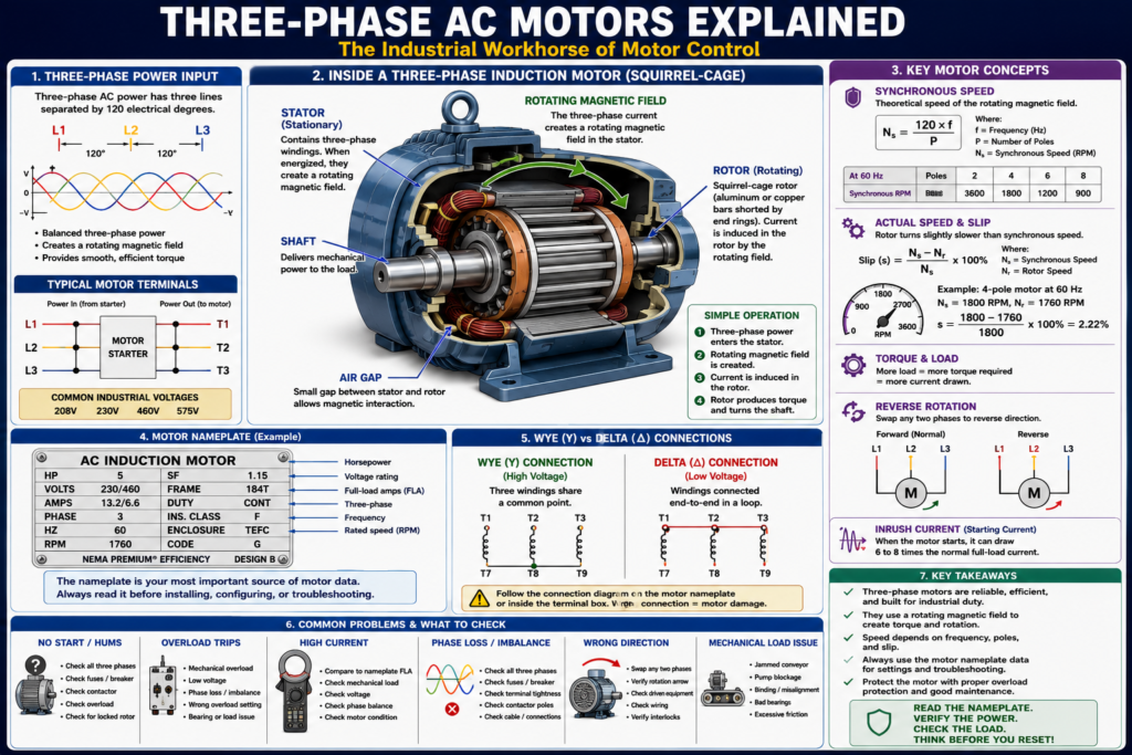
Three-phase AC motors are one of the most common types of motors used in industrial automation. They are found in conveyors, pumps, compressors, fans, mixers, agitators, packaging machines, and many other production systems.
For an automation technician, understanding three-phase motors is essential because most industrial motor control systems are built around them.
A simple way to think about it:
A three-phase AC motor converts three-phase electrical power into rotating mechanical motion.
The motor itself may look simple from the outside, but inside it is using magnetic fields, current, torque, and rotation to drive industrial equipment.
AC induction motors are the dominant motor technology in use today and represent more than 90 percent of installed motor capacity. It also explains that induction motors are available in single-phase and three-phase configurations and may be used with fixed-speed operation or adjustable-speed drives.
What Is a Three-Phase AC Motor?
A three-phase AC motor is a motor designed to operate from a three-phase power supply.
Typical industrial three-phase voltages include:
208 VAC
230 VAC
460 VAC
575 VAC
A three-phase motor usually has three power input lines:
L1
L2
L3
And motor load terminals commonly identified as:
T1
T2
T3
When three-phase power is applied to the motor, the motor creates a rotating magnetic field. This rotating magnetic field causes the rotor to turn.
In simple terms:
Three-phase power → rotating magnetic field → rotor turns → shaft produces motionWhy Three-Phase Motors Are So Common in Industry
Three-phase motors are popular in industrial environments because they are:
- Reliable
- Efficient
- Rugged
- Self-starting
- Good for continuous duty
- Available in many horsepower ratings
- Compatible with contactors, starters, soft starters, and VFDs
- Well suited for pumps, fans, conveyors, compressors, and mixers
Larger horsepower single-phase motors are not normally used because they are less efficient compared to three-phase motors. It also notes that three-phase motors are self-starting, unlike many single-phase motors.
This is why three-phase motors are everywhere in manufacturing.
Basic Parts of a Three-Phase AC Motor
A three-phase induction motor has two main electrical/mechanical parts:
1. Stator
The stator is the stationary part of the motor.
It contains the motor windings. These windings are connected to the three-phase power supply.
When three-phase current flows through the stator windings, it creates a rotating magnetic field.
2. Rotor
The rotor is the rotating part of the motor.
The rotor sits inside the stator and is connected to the motor shaft.
As the stator’s rotating magnetic field moves, it induces current into the rotor. This produces torque and causes the rotor to turn.
Most common AC motors use a squirrel-cage rotor configuration, where aluminum or copper bars are embedded in the rotor. It also notes that there is no direct physical electrical connection to the squirrel cage; current is induced by the rotating magnetic field of the stator.
Squirrel-Cage Induction Motor
The most common industrial three-phase motor is the squirrel-cage induction motor.
It is called “squirrel cage” because the rotor construction looks similar to a cage, with conductive bars connected by end rings.
Advantages of squirrel-cage motors:
- Simple construction
- Low maintenance
- No brushes
- Rugged design
- Reliable operation
- Good for industrial environments
- Works well with across-the-line starters and VFDs
This is the type of motor most automation technicians will see in the field.
How a Three-Phase Motor Rotates
A three-phase power system has three AC waveforms separated by 120 electrical degrees.
These phases are:
Phase A
Phase B
Phase C
or commonly:
L1
L2
L3
Because the three phases rise and fall at different times, the magnetic field inside the motor appears to rotate.
That rotating magnetic field pulls the rotor around.
A simple way to explain it:
L1, L2, and L3 energize the stator windings in sequence.
This creates a rotating magnetic field.
The rotor follows that rotating field.
The motor shaft turns.
Rotating magnetic field and induction motor operation as core topics under three-phase AC motors.
What Is Induction?
Three-phase induction motors are called induction motors because current is induced into the rotor.
There is no direct electrical connection between the power supply and the rotor in a squirrel-cage induction motor.
Instead:
Stator magnetic field induces current into the rotor.
Rotor current creates its own magnetic field.
The interaction between magnetic fields creates torque.
This is similar in concept to how a transformer transfers energy magnetically, except the motor converts that electromagnetic interaction into rotation.
Motor Speed and Frequency
The speed of an AC motor is related to:
- Supply frequency
- Number of motor poles
- Slip
The basic synchronous speed formula is:
Synchronous Speed = (120 × Frequency) / Number of PolesAt 60 Hz, common synchronous speeds are:
| Number of Poles | Synchronous Speed |
|---|---|
| 2 poles | 3600 RPM |
| 4 poles | 1800 RPM |
| 6 poles | 1200 RPM |
| 8 poles | 900 RPM |
However, an induction motor usually runs slightly below synchronous speed because of slip.
That is why a 4-pole motor may have a nameplate speed such as:
1760 RPMinstead of exactly:
1800 RPMAC motor speed is determined by the number of poles and the frequency of the supply voltage, and that nameplate speed is an approximate speed at rated load.
What Is Slip?
Slip is the difference between the rotating magnetic field speed and the actual rotor speed.
For an induction motor to produce torque, the rotor must rotate slightly slower than the rotating magnetic field.
Simple concept:
Synchronous speed = speed of rotating magnetic field
Rotor speed = actual shaft speed
Slip = difference between them
Example:
Synchronous speed: 1800 RPM
Motor nameplate speed: 1760 RPM
Slip: 40 RPM
Slip increases when load increases. If the motor is heavily loaded, rotor speed drops slightly and current increases.
Three-Phase Motor Terminals
A basic three-phase motor power circuit uses:
L1 → T1
L2 → T2
L3 → T3
These terminals feed the motor windings.
On the starter side:
L1, L2, L3 = incoming line power
T1, T2, T3 = outgoing motor/load power
On the motor side, lead markings may depend on the motor type and lead count.
For many motors, especially dual-voltage motors, you may see leads such as:
T1 through T9Wye and Delta Connections
Three-phase motor windings are commonly connected internally or externally in one of two configurations:
Wye (Y)
Delta (Δ)
All three-phase motors are wired so their phases are connected in either wye or delta configuration.
Wye Connection
A wye connection has one end of each phase connected together at a common point.
General concept:
Three windings share a common center point.Delta Connection
A delta connection connects the three phase windings end-to-end in a closed loop.
General concept:
The windings form a triangle-like loop.Both types are common. Always follow the motor nameplate connection diagram.
Dual-Voltage Three-Phase Motors
Many industrial motors can be connected for more than one voltage.
Example:
230 / 460 VACThis type of motor must be wired correctly based on the supply voltage.
General rule:
Low voltage = windings connected in parallel
High voltage = windings connected in series
Three-phase motors are commonly manufactured for different voltage levels, such as 208/230/460 V, and that the motor nameplate or connection diagram must be followed for the correct connection method.
Important field warning:
Never guess motor lead connections. Always use the nameplate or connection diagram.
Incorrect motor connections can cause:
- High current
- Low torque
- Failure to start
- Overload trips
- Motor overheating
- Winding damage
Reversing a Three-Phase Motor
One of the useful characteristics of a three-phase motor is that its direction can be reversed by swapping any two phases.
Example:
Normal rotation:
L1 → T1
L2 → T2
L3 → T3
Reverse rotation:
L1 → T2
L2 → T1
L3 → T3
To reverse the direction of rotation of any three-phase wye- or delta-connected motor, you simply reverse or interchange any two line leads.
This is the basis of a reversing starter.
A reversing starter uses:
- Forward contactor
- Reverse contactor
- Mechanical interlock
- Electrical interlock
- Overload relay
This will be covered in more detail in a later post.
Across-the-Line Starting
A common way to start a three-phase motor is across-the-line starting.
Defines an across-the-line starter as a general-purpose starter that connects incoming power directly to the motor.
Basic operation:
Press Start
    ↓
Contactor coil energizes
    ↓
Main contacts close
    ↓
Full voltage is applied to motor
    ↓
Motor starts
Across-the-line starting is simple and common, but it creates high starting current.
Inrush current is the current drawn when a motor is first switched on and may be 6 to 8 times normal running current.
Inrush Current
When a motor starts, it draws more current than it does while running.
This high starting current is called inrush current.
Example:
Motor running current: 10 A
Possible starting current: 60–80 A
Inrush current is normal during startup, but it must be considered when selecting:
- Starter
- Overload relay
- Breaker
- Fuses
- Wire size
- VFD or soft starter
- Control strategy
Large motors may require special starting methods to reduce current and mechanical stress.
Torque and Load
A motor produces torque to move the load.
Torque is the twisting force that rotates the shaft.
Common loads include:
- Conveyor belt
- Pump impeller
- Fan blade
- Mixer shaft
- Compressor
- Gearbox
- Agitator
If the load becomes too heavy, the motor draws more current.
Examples:
Conveyor jam → motor current increases
Pump blockage → motor current increases
Bearing failure → motor current increases
Mixer overloaded → motor current increases
If excessive current continues too long, the overload relay should trip to protect the motor.
Three-Phase Motor and Overload Protection
Three-phase motors require proper overload protection.
The overload relay monitors motor current and opens the control circuit if current remains too high for too long.
Typical motor starter:
Contactor + Overload Relay = Motor StarterThe overload relay protects the motor from:
- Excessive load
- Locked rotor
- Phase loss
- Sustained overcurrent
- Overheating
Defines overload protection as a device or system that prevents a motor from drawing too much current, overheating, and burning out.
Phase Loss / Single Phasing
Phase loss happens when one of the three phases is missing.
This can be caused by:
- Blown fuse
- Bad breaker pole
- Loose wire
- Bad contactor pole
- Failed disconnect contact
- Damaged cable
- Utility issue
Symptoms may include:
- Motor hums
- Motor does not start
- Motor runs hot
- Motor has low torque
- Overload trips
- Current imbalance
- VFD fault
Overload protection may also protect against loss of a phase on a three-phase system.
Phase loss should be taken seriously because it can quickly damage a motor.
Motor Nameplate Data for Three-Phase Motors
Before replacing, troubleshooting, or configuring a three-phase motor, always check the nameplate.
Important nameplate data includes:
Voltage
Full-load amps
Horsepower
Phase
Frequency
RPM
Service factor
Frame
Duty
Enclosure
Connection diagram
This information is used for:
- Overload setting
- VFD configuration
- Starter selection
- Replacement selection
- Troubleshooting current draw
- Verifying lead connections
Practical rule:
Do not troubleshoot by guessing. Read the motor nameplate first.
Three-Phase Motors with VFDs
Many three-phase AC motors are controlled by a Variable Frequency Drive, or VFD.
A VFD controls motor speed by changing the frequency and voltage supplied to the motor.
Basic VFD concept:
AC input → Rectifier → DC bus → Inverter → Variable frequency output → MotorVFD as a device that controls the speed of an AC motor by varying the frequency supplied to the motor and regulating output voltage in proportion to frequency.
Common VFD parameters from the motor nameplate include:
Motor Voltage
Motor FLA
Motor Frequency
Motor RPM
Motor HP
If these values are wrong, the VFD may not protect or control the motor correctly.
Common Three-Phase Motor Problems
| Symptom | Possible Cause |
|---|---|
| Motor does not start | No power, overload trip, bad contactor, phase loss |
| Motor hums but does not rotate | Phase loss, locked rotor, mechanical jam |
| Motor trips overload | Overload, low voltage, phase imbalance, bearing issue |
| Motor runs hot | Overloaded, poor cooling, high current, wrong voltage |
| Motor rotates wrong direction | Two phases reversed |
| Motor vibrates | Bearing problem, misalignment, mechanical imbalance |
| Motor current unbalanced | Phase issue, bad connection, winding problem |
| VFD faults on start | Wrong parameters, motor issue, short, overload |
Troubleshooting Three-Phase Motors
Use a structured approach.
Step 1 — Safety First
Follow plant safety procedures and lockout/tagout requirements before working on electrical or mechanical equipment.
Do not assume a stopped motor is safe.
Step 2 — Check the Nameplate
Record:
Voltage
FLA
HP
Phase
Hz
RPM
Connection diagram
Step 3 — Check the Power Circuit
Verify:
L1-L2
L2-L3
L1-L3
Check for:
- Missing phase
- Low voltage
- Voltage imbalance
- Blown fuse
- Bad contactor pole
- Loose connection
Step 4 — Check the Control Circuit
Verify:
- Stop circuit healthy
- Start command present
- Overload contact closed
- Safety circuit OK
- PLC output ON, if PLC controlled
- Contactor coil voltage present
Step 5 — Check Motor Current
Measure current on each phase:
T1
T2
T3
Compare measured current to nameplate FLA.
If current is high on all phases, check mechanical load.
If current is unbalanced, check phase supply, connections, contactor, overload, or motor windings.
Step 6 — Check the Mechanical Load
Look for:
- Jammed conveyor
- Locked pump
- Bad bearing
- Gearbox problem
- Belt tension issue
- Misalignment
- Product buildup
Many electrical overload trips are caused by mechanical problems.
PLC Motor Control View
In a PLC-controlled three-phase motor system, the PLC usually does not switch motor power directly.
Instead, the PLC controls:
Starter coil
Interposing relay
VFD run command
Soft starter input
Typical PLC tags:
Motor_Start_Request
Motor_Run_Command
Motor_Starter_Output
Motor_Run_Feedback
Motor_Overload_OK
Motor_Failed_To_Start
Motor_Overload_Fault
A clean structure:
Request → Permissives → Command → Output → Feedback → Fault DetectionExample:
If Motor_Run_Command is ON
and Motor_Run_Feedback does not turn ON within 3 seconds,
then latch Motor_Failed_To_Start_Fault.
This helps detect when the motor was commanded but did not actually run.
Practical Field Example
A three-phase conveyor motor does not start.
A technician should not immediately replace the motor.
A better method:
- Check HMI or panel fault.
- Check overload status.
- Check control voltage.
- Check Start command.
- Check contactor coil voltage.
- Verify contactor pulls in.
- Measure voltage at L1/L2/L3.
- Measure voltage at T1/T2/T3 with the contactor energized.
- Check motor current.
- Inspect conveyor for jam or mechanical binding.
- Confirm motor feedback to PLC.
Field mindset:
Prove where the problem is: control, power, protection, feedback, or mechanical load.
Industrial Pro Tips
Pro Tip 1 — Always Check All Three Phases
Do not check only one phase. A missing phase can make a motor hum, overheat, or trip overload.
Pro Tip 2 — Compare Current to Nameplate FLA
The nameplate FLA tells you what the motor should draw at rated load.
Pro Tip 3 — Rotation Matters
If a pump, fan, or conveyor runs backward, it may not work correctly and may be damaged.
Pro Tip 4 — Do Not Keep Resetting Overloads
An overload trip is a symptom. Find the cause.
Pro Tip 5 — Separate Electrical and Mechanical Troubleshooting
A motor may trip because of mechanical load, not because the motor is bad.
Quick Summary
Three-phase AC motor = common industrial motor

Stator = stationary winding section

Rotor = rotating section connected to shaft

Squirrel-cage induction motor = most common industrial type

Three-phase power creates a rotating magnetic field

Rotor turns because current is induced into it

Speed depends on frequency and number of poles

Slip is normal in induction motors

Swap any two phases to reverse rotation

Always check nameplate data before replacing or troubleshooting
Final Thoughts
Three-phase AC motors are the backbone of industrial motor control. They are rugged, efficient, self-starting, and capable of driving many types of industrial equipment.
For automation technicians, understanding three-phase motors is not only about knowing that L1, L2, and L3 power the motor. It is about understanding how the motor creates rotation, how current relates to load, how overload protection works, how phase loss affects operation, how to read the nameplate, and how the PLC or VFD controls the motor.
When troubleshooting, do not guess. Use the drawings, read the nameplate, verify all three phases, check the control circuit, measure current, and inspect the mechanical load.
The better you understand three-phase motors, the better you become at diagnosing real industrial equipment problems.