10. Wye/Delta and Motor Lead Connections Explained (10 of 22)
Understanding 3-Phase Motor Wiring, Low Voltage, High Voltage, and Rotation
Introduction
Three-phase motors are common in industrial automation, but one area that can confuse technicians is motor lead connections.
When you open a motor junction box, you may see several numbered leads such as:
T1, T2, T3, T4, T5, T6, T7, T8, T9At first, this can look intimidating. However, once you understand the purpose of the motor leads, the difference between wye and delta, and how low-voltage and high-voltage connections work, the concept becomes much easier.
A simple way to remember it:
Motor leads are the access points to the internal windings of the motor. The way those leads are connected determines how the motor windings are arranged for the supply voltage.
The motor control material explains that three-phase motors are connected in either wye (Y) or delta (Δ) configurations, and that dual-voltage motors must be connected according to the motor nameplate or connection diagram.
Why Motor Lead Connections Matter
Correct motor lead connections are critical.
Wrong connections can cause:
- Motor failure to start
- Low torque
- Excessive current
- Overload trips
- Motor overheating
- Winding damage
- Wrong direction of rotation
- Equipment damage
Before connecting or replacing a motor, always verify:
1. Supply voltage
2. Motor nameplate voltage
3. Motor wiring diagram
4. Lead numbers
5. Overload setting
6. Rotation direction
Never guess motor lead connections. Always follow the motor nameplate, the connection diagram inside the motor junction box, or approved plant documentation.
What Are Motor Leads?
Motor leads are the wires that come from the internal motor windings.
In a three-phase motor, the stator has three phase windings:
Phase A
Phase B
Phase C
Each phase winding has leads that allow the windings to be connected in different ways depending on the motor design.
Common lead markings include:
T1 through T3
T1 through T6
T1 through T9
T1 through T12
For this post, we will focus mainly on the common 9-lead dual-voltage three-phase motor, because it is very common in industrial motor control training and field applications.
Wye and Delta Connections
Three-phase motor windings are commonly arranged in one of two configurations:
Wye (Y)
Delta (Δ)
Both configurations are used in industrial motors.
Wye Connection
A wye connection has one end of each phase winding connected together at a common point.
Simple concept:
Three windings share a common center point.It is called “wye” because the winding arrangement resembles the letter Y.
Basic idea:
        Phase A
          |
          |
Phase B --+-- Phase C
       common point
In many dual-voltage wye motors, the winding sections can be connected in series for high voltage or parallel for low voltage.
Delta Connection
A delta connection connects the three phase windings end-to-end in a closed loop.
Simple concept:
The windings form a triangle-like loop.It is called “delta” because the arrangement resembles the Greek letter delta:
ΔBasic idea:
Phase A
 /    \
Phase B -- Phase C
Delta-connected motors are also common in industrial applications.
Wye vs Delta: Simple Comparison
| Feature | Wye (Y) | Delta (Δ) |
|---|---|---|
| Shape | Looks like a Y | Looks like a triangle |
| Common point | Has a common center point | Windings connected end-to-end |
| Used in | Many industrial motors | Many industrial motors |
| Lead connection | Depends on motor design | Depends on motor design |
| Technician rule | Follow nameplate diagram | Follow nameplate diagram |
The most important point is not memorizing every possible connection. The most important point is understanding the concept and following the correct diagram for that motor.
Dual-Voltage Motors
Many three-phase motors are designed to operate at two different voltages.
Common example:
230 / 460 VACor:
208-230 / 460 VACThis means the same motor can be connected for either lower voltage or higher voltage.
The motor does not “automatically know” the voltage. The leads must be connected correctly.
Low Voltage vs High Voltage
For many dual-voltage motors:
Low voltage = winding sections connected in parallel
High voltage = winding sections connected in series
Parallel Connection for Low Voltage
In a low-voltage connection, winding sections are connected in parallel.
Simple idea:
More current paths are available.
Each winding section receives the correct voltage.
Series Connection for High Voltage
In a high-voltage connection, winding sections are connected in series.
Simple idea:
Voltage is divided across winding sections.
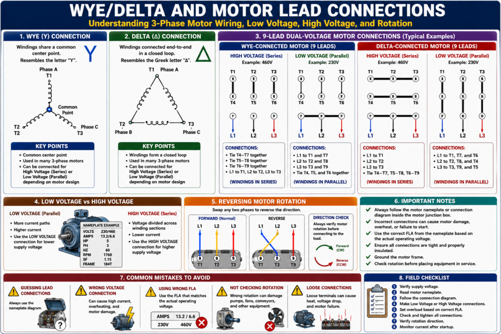
Each winding section still receives the correct voltage.Typical nine-lead dual-voltage wye-connected three-phase motor, each phase coil is divided into two equal parts and connected in series for high-voltage operation or parallel for low-voltage operation.
9-Lead Motor Basics
A common dual-voltage three-phase motor has nine leads:
T1, T2, T3, T4, T5, T6, T7, T8, T9These leads are connected according to the motor nameplate diagram.
The exact connection depends on whether the motor is internally configured as wye or delta.
Important:
Do not assume every 9-lead motor is wired the same. Always verify the nameplate diagram.
9-Lead Wye Motor Connections
For a typical 9-lead wye motor, the high-voltage connection usually places winding sections in series.
A practical high-voltage wye exercise where:
T7 and T4 tie together
T8 and T5 tie together
T9 and T6 tie together
T1 connects to Line 1
T2 connects to Line 2
T3 connects to Line 3
Typical 9-Lead Wye High Voltage Example
L1 → T1
L2 → T2
L3 → T3

Tie T4-T7
Tie T5-T8
Tie T6-T9
This places the winding sections in series for high-voltage operation.
Typical 9-Lead Wye Low Voltage Concept
For low voltage, winding sections are generally connected in parallel.
A typical concept is:
L1 connects to T1 and T7
L2 connects to T2 and T8
L3 connects to T3 and T9
T4, T5, T6 tied together
This allows the motor to operate at the lower voltage rating.
Always verify this with the specific motor diagram.
9-Lead Delta Motor Connections
Delta motors also use low-voltage and high-voltage connection patterns, but the tie points are different from wye.
A practical low-voltage delta exercise where:
T1, T7, and T6 tie together and connect to Line 1
T2, T8, and T4 tie together and connect to Line 2
T3, T9, and T5 tie together and connect to Line 3
Typical 9-Lead Delta Low Voltage Example
L1 → T1 + T7 + T6
L2 → T2 + T8 + T4
L3 → T3 + T9 + T5
Again, do not apply this blindly to every motor. Confirm the nameplate diagram.
Why High Voltage Uses Lower Current
A common question is:
“Why does the same motor draw less current at 460 V than at 230 V?”
The motor produces roughly the same horsepower, but voltage and current are related.
A dual-voltage motor may show:
VOLTS: 230/460
AMPS: 13.2/6.6
At 460 V, the current is about half the current at 230 V.
This is why the overload setting must match the actual operating voltage.
If the motor is connected to 460 V, use the 460 V FLA value.
If the motor is connected to 230 V, use the 230 V FLA value.
Motor Nameplate Is the Authority
The motor nameplate or connection diagram is the official guide for wiring the motor.
You may find the connection diagram:
- On the motor nameplate
- Inside the motor junction box cover
- On a connection plate
- In the motor manual
- In plant documentation
Motor connection diagrams may be found on the nameplate, inside the motor conduit box, or on a special connection plate, and that they indicate specific connections for dual-voltage motors.
Practical rule:
If the nameplate and your memory disagree, trust the nameplate.
Reversing Motor Rotation
For a three-phase motor, reversing rotation is simple electrically:
Swap any two phases.
Example normal rotation:
L1 → T1
L2 → T2
L3 → T3
Reverse rotation:
L1 → T2
L2 → T1
L3 → T3
The motor control textbook states that to reverse the direction of rotation of any three-phase wye- or delta-connected motor, you simply reverse or interchange any two line leads.
Why Rotation Matters
Wrong rotation can cause real equipment damage.
Examples:
| Equipment | Risk of Wrong Rotation |
|---|---|
| Pump | No flow, seal damage, impeller issue |
| Fan | Low airflow or wrong airflow direction |
| Conveyor | Product moves backward |
| Mixer | Poor mixing or mechanical stress |
| Screw conveyor | Product backs up |
| Gearbox system | Unexpected motion |
Before returning equipment to service, verify rotation direction according to the machine requirement.
Connection Mistakes to Avoid
Mistake 1 — Guessing Lead Connections
Never connect leads based only on memory.
Always use the nameplate diagram.
Mistake 2 — Mixing Up Low and High Voltage Connections
A 230/460 V motor wired for 230 V and connected to 460 V can be damaged.
A motor wired for 460 V but connected to 230 V may have low torque and fail to start.
Mistake 3 — Using the Wrong FLA
Dual-voltage motors have different current ratings.
Use the FLA that matches the operating voltage.
Mistake 4 — Not Checking Rotation
After connecting or replacing a three-phase motor, always verify rotation before normal operation.
Mistake 5 — Ignoring Lead Markings
Damaged or missing lead markers can cause confusion. If lead markings are unclear, follow approved testing and identification procedures before connecting.
Field Checklist Before Connecting a Motor
Before connecting a three-phase motor, verify:
1. Motor tag number
2. Supply voltage
3. Motor nameplate voltage
4. Lead connection diagram
5. Low-voltage or high-voltage configuration
6. Correct overload setting
7. Ground connection
8. Terminal tightness
9. Rotation direction
10. Mechanical load condition
This checklist helps prevent common motor replacement mistakes.
Troubleshooting Motor Lead Connection Problems
Symptom: Motor Trips Overload Immediately
Possible causes:
- Incorrect lead connection
- Wrong voltage connection
- Mechanical jam
- Locked rotor
- Phase loss
- Shorted winding
Symptom: Motor Hums and Does Not Start
Possible causes:
- Missing phase
- Incorrect lead connection
- Low voltage
- Locked rotor
- Open winding
- Bad contactor pole
Symptom: Motor Runs Backward
Possible cause:
- Phase sequence reversed
Correction:
Swap any two motor leads or output phases, following safe procedures.Symptom: Motor Runs Hot
Possible causes:
- Wrong voltage connection
- Overloaded motor
- Low voltage
- Phase imbalance
- Wrong overload setting
- Poor cooling
- Wrong motor for application
PLC and VFD Considerations
In a PLC or VFD-controlled system, the motor lead connections still matter.
The PLC may command the motor correctly, but if the motor leads are wrong, the motor can still fail or run incorrectly.
With a VFD:
- Verify motor nameplate voltage
- Enter correct motor FLA
- Enter correct motor RPM
- Verify motor frequency
- Verify motor direction
- Check VFD output wiring
- Follow drive manufacturer requirements
For VFD applications, do not swap input power to reverse motor direction unless the drive documentation allows it. Normally, motor direction is changed by swapping output leads or changing drive parameters, depending on the procedure and system design.
Practical Field Example
A 5 HP motor is replaced.
Nameplate:
VOLTS: 230/460
AMPS: 13.2/6.6
PHASE: 3
RPM: 1760
Plant supply:
460 VACCorrect approach:
1. Connect motor leads for high voltage according to the nameplate.
2. Set overload based on 6.6 A, not 13.2 A.
3. Verify all terminal connections are tight.
4. Jog or bump test the motor if allowed by procedure.
5. Confirm correct rotation.
6. Monitor current during startup and running.
Incorrect approach:
Guessing the lead connection
Using 13.2 A overload setting on 460 V
Starting motor without checking rotation
Ignoring motor nameplate diagram
Industrial Pro Tips
Pro Tip 1 — Take Pictures Before Disconnecting
Before removing an old motor, take clear photos of:
- Motor nameplate
- Junction box wiring
- Lead connections
- Terminal markings
- Ground connection
- Rotation arrow
- Coupling or belt arrangement
Pro Tip 2 — Label Leads Clearly
If motor lead markers are damaged, fix the identification before disconnecting if possible.
Pro Tip 3 — Use the Correct FLA
A dual-voltage motor has two FLA values. Use the one that matches the actual supply voltage.
Pro Tip 4 — Verify Rotation Safely
A bump test may be used in some plants, but only under approved procedures and with the equipment safe to move.
Pro Tip 5 — Do Not Assume Wye or Delta by Looking Only at the Leads
Always check the diagram. Motors can have different internal designs.
Quick Summary
Wye (Y) = windings share a common point.

Delta (Δ) = windings are connected end-to-end in a loop.

Dual-voltage motor = can run on low or high voltage depending on lead connection.

Low voltage = windings commonly connected in parallel.

High voltage = windings commonly connected in series.

T1-T9 = common lead markings on 9-lead three-phase motors.

Swap any two phases to reverse a three-phase motor.

Always follow the motor nameplate connection diagram.
Final Thoughts
Wye, delta, and motor lead connections are essential knowledge for automation technicians working with industrial motors.
The most important lesson is not to memorize one diagram and apply it everywhere. The most important lesson is to understand the principle and verify the actual motor nameplate or connection diagram before making connections.
Wrong lead connections can damage a motor, trip overloads, create low torque, or cause the machine to run in the wrong direction.
A good technician verifies the supply voltage, reads the nameplate, follows the connection diagram, sets the overload correctly, checks rotation, and confirms current draw after startup.
Motor lead connections are not just wiring details. They are part of reliable and safe industrial motor control.