6. Contactors and Motor Starters Explained for Industrial Motor Control (6 of 22)
The Hardware Behind Industrial Motor Control
Introduction
In industrial motor control, two of the most common devices inside a control panel are the contactor and the motor starter.
At first, they may look similar, and many technicians use the terms almost interchangeably. However, they are not exactly the same.
A simple way to understand the difference is:
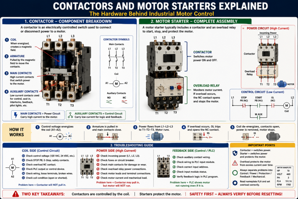
A contactor switches motor power ON and OFF.
A motor starter switches motor power and also provides overload protection.
Understanding contactors and motor starters is essential for troubleshooting motors, reading electrical drawings, working with PLC outputs, and diagnosing common field problems such as a motor not starting, a contactor not pulling in, an overload trip, or a motor running without feedback.
What Is a Contactor?
A contactor is an electrically controlled switching device used to connect or disconnect power to a load, commonly an electric motor.
Contactor as an operating device that connects or disconnects the motor from the power supply using an electromagnetic circuit, coil, and magnetic armature frame.
In simple terms:
A contactor is like a heavy-duty electrical switch controlled by a coil.
Instead of manually turning a switch ON and OFF, the control circuit energizes the contactor coil. When the coil energizes, the contactor closes its main contacts and allows power to flow to the motor.
Main Parts of a Contactor
A typical contactor includes:
| Part | Purpose |
|---|---|
| Coil | Creates a magnetic field when energized |
| Armature | Mechanical moving part pulled by the magnetic field |
| Main contacts | Switch motor power ON and OFF |
| Auxiliary contacts | Used for seal-in, feedback, interlocks, and status |
| Arc chute / arc suppression area | Helps control arcing when contacts open |
| Terminals | Connection points for power and control wiring |
Armature as the component of a magnetic contactor that holds the movable contacts, and defines contacts as the parts of a contactor that make and break the electrical connection.
How a Contactor Works
A contactor works through electromagnetism.
Basic sequence:
- Control voltage is applied to the contactor coil.
- The coil creates a magnetic field.
- The magnetic field pulls in the armature.
- The main contacts close.
- Power flows through the contactor to the motor.
- When coil voltage is removed, the magnetic field collapses.
- The armature releases.
- Main contacts open.
- Power is removed from the motor.
Simple control-to-power relationship:
Control circuit energizes coil
        ↓
Contactor pulls in
        ↓
Main contacts close
        ↓
Power circuit feeds motor
        ↓
Motor runs
This is why the contactor is the bridge between the control circuit and the power circuit.
Coil Side vs Power Side
A contactor has two important sides:
Control Side
The control side energizes the coil.
Typical coil voltages may include:
24 VDC
120 VAC
208 VAC
240 VAC
480 VAC
The coil terminals are often labeled:
A1 and A2The control circuit may include:
- Stop pushbutton
- Start pushbutton
- Overload NC contact
- PLC output
- Safety relay contact
- HOA selector switch
- Control transformer
Power Side
The power side switches the motor current.
Typical line and load terminals:
L1, L2, L3 = incoming line power
T1, T2, T3 = outgoing motor/load power
When the contactor is open, L1/L2/L3 do not connect to T1/T2/T3.
When the contactor closes, power flows from:
L1 → T1
L2 → T2
L3 → T3
What Are Main Contacts?
Main contacts are the high-current contacts that carry motor power.
They are part of the power circuit.
When the contactor coil energizes, these contacts close and apply voltage to the motor.
When the coil de-energizes, these contacts open and remove voltage from the motor.
Because main contacts carry motor current, they are exposed to:
- Inrush current
- Arcing
- Heat
- Mechanical wear
- Contact bounce
- Oxide buildup
- Pitting or burning
Arcing as a condition where high voltage leaps across the open space between contacts, and defines contact bounce as a condition caused by contactor contacts slamming against each other and rebounding.
What Are Auxiliary Contacts?
Auxiliary contacts are lower-current contacts mechanically linked to the contactor.
They are used in the control circuit, not usually for motor power.
Auxiliary contacts may be:
Normally Open (NO)
Normally Closed (NC)
Common uses:
- Seal-in circuit
- Motor run feedback
- Electrical interlocking
- Pilot light control
- PLC input status
- Forward/reverse interlocking
- Alarm logic
Example:
M coil energizes
        ↓
M auxiliary contact closes
        ↓
PLC receives Motor_Run_Feedback
Important concept:
Main contacts switch motor power. Auxiliary contacts provide control logic and status.
What Is a Motor Starter?
A motor starter is a device or assembly used to start and stop a motor while also providing motor protection.
Defines a starter as a device that controls the use of electrical power to equipment, usually a motor.
In many basic industrial applications, a magnetic motor starter includes:
Contactor + Overload RelayA simple way to remember it:
A contactor controls motor power.
A starter controls motor power and protects the motor from overload.
Contactor vs Motor Starter
| Feature | Contactor | Motor Starter |
|---|---|---|
| Switches motor power | Yes | Yes |
| Has a coil | Yes | Yes |
| Has main contacts | Yes | Yes |
| Has auxiliary contacts | Often | Often |
| Provides overload protection by itself | No | Yes, when combined with overload relay |
| Typical use | Switching loads | Starting and protecting motors |
A contactor alone can switch a motor, but it does not provide complete motor protection.
A motor starter normally includes overload protection to protect the motor from excessive current over time.
What Is an Overload Relay?
An overload relay protects the motor from drawing too much current for too long.
The motor control glossary defines overload protection as a device or system that prevents an electric motor from drawing too much current, overheating, and burning out. It also defines an overload relay as a relay that responds to electrical overloads and operates at a preset value.
A motor overload may happen because of:
- Mechanical jam
- Bearing failure
- Conveyor overload
- Pump blockage
- Low voltage
- Phase loss
- Incorrect motor wiring
- Motor undersized for the load
- Locked rotor condition
The overload relay normally has:
- A power section that monitors motor current.
- A control contact that opens the control circuit when the overload trips.
Important Concept: The Overload Relay Stops the Control Circuit
In many motor starters, the overload relay does not directly open the main power contacts like a breaker.
Instead, it opens a normally closed overload contact in the control circuit.
Example:
L1 ----[/ STOP]----[ START ]----[/ OL ]----( M )
              |----[ M AUX ]----|
L2
If the overload trips:
OL contact opens
        ↓
M coil de-energizes
        ↓
Contactor opens
        ↓
Motor stops
This is why the overload relay is connected to both the power side and the control side.
Overload Relay vs Circuit Breaker
This is a major troubleshooting concept.
| Device | Protects Against | Response Type |
|---|---|---|
| Circuit breaker / Fuse | Short circuit and high fault current | Fast trip |
| Overload relay | Excessive motor current over time | Time-based trip |
| Contactor | Switching ON/OFF | No protection by itself |
A breaker protects the circuit from high fault current.
An overload relay protects the motor from overheating due to excessive load over time.
They are not the same device and should not be treated as the same during troubleshooting.
Across-the-Line Starter
The most basic motor starter is the across-the-line starter.
The glossary describes an across-the-line starter as a commonly used general-purpose starter that connects incoming power directly to the motor.
Basic sequence:
Press Start
    ↓
Contactor coil energizes
    ↓
Main contacts close
    ↓
Full voltage is applied to motor
    ↓
Motor starts
This method is simple and common, but it produces high starting current.
The glossary also explains that inrush current is the current drawn when a motor is first switched on and may be 6 to 8 times the normal running current.
Why Contactors Wear Out
Contactors are mechanical devices. Every time they open or close, the contacts experience stress.
Common causes of contactor wear include:
- Frequent starting and stopping
- High inrush current
- Motor overload conditions
- Loose terminals
- Heat
- Dust or contamination
- Contact arcing
- Contact bounce
- Vibration
- Undervoltage on the coil
Over time, contactor contacts may become:
- Burned
- Pitted
- Welded
- Oxidized
- Loose
- Mechanically stuck
Defines oxide as buildup that forms over time on contacts that are repeatedly opened and closed.
Common Contactor Problems
| Symptom | Possible Cause |
|---|---|
| Contactor does not pull in | No coil voltage, bad coil, open Stop/OL/safety contact |
| Contactor chatters | Low control voltage, loose wire, weak coil, bad shading coil |
| Contactor pulls in but motor does not run | Bad main contacts, blown fuse, open overload, missing phase |
| Contactor hums loudly | Coil issue, low voltage, mechanical obstruction |
| Contactor sticks ON | Welded contacts, mechanical failure |
| Contacts burn quickly | Overload, high cycling, incorrect sizing, loose connections |
Troubleshooting a Contactor
When troubleshooting a contactor, divide it into control side and power side.
Control Side Checks
Ask:
- Is control voltage present?
- Is the Stop button closed?
- Is the overload contact closed?
- Is the safety circuit healthy?
- Is the PLC output ON?
- Is voltage present at A1/A2?
- Is the coil rated for the voltage being applied?
- Is the coil open or shorted?
Power Side Checks
Ask:
- Is line voltage present at L1/L2/L3?
- Does the contactor close mechanically?
- Is voltage present at T1/T2/T3 when closed?
- Are all three phases present?
- Are fuses good?
- Are main contacts burned or pitted?
- Is the overload passing power?
- Is the motor receiving voltage?
A practical rule:
If the contactor does not pull in, troubleshoot the control circuit.

If the contactor pulls in but the motor does not run, troubleshoot the power circuit.
Troubleshooting a Motor Starter
A motor starter includes both contactor and overload relay, so troubleshooting must include both.
Checklist:
1. Check incoming power.
2. Check control voltage.
3. Check Stop/E-Stop/safety path.
4. Check overload reset/status.
5. Check coil voltage.
6. Check contactor movement.
7. Check output voltage to motor.
8. Check motor current.
9. Check feedback signal to PLC.
10. Check mechanical load.
Important field mindset:
Do not assume the motor is bad. Prove whether the issue is control, power, protection, feedback, or mechanical load.
Contactor Feedback to PLC
In modern motor control, a contactor auxiliary contact is often wired back to the PLC as feedback.
Example tags:
Motor_Run_Command
Motor_Starter_Output
Motor_Run_Feedback
Motor_Failed_To_Start
Sequence:
PLC commands motor starter output
        ↓
Contactor coil energizes
        ↓
Auxiliary contact closes
        ↓
PLC sees motor run feedback
If the PLC commands the motor but does not receive feedback, the program can generate a fault.
Example:
If Motor_Starter_Output is ON
and Motor_Run_Feedback does not turn ON within 3 seconds,
then latch Motor_Failed_To_Start_Fault.
This is a professional way to detect:
- Bad contactor coil
- Bad auxiliary contact
- Tripped overload
- Broken wire
- Failed output module
- Missing control voltage
Electrical Interlocking with Contactors
Contactors are also used for interlocking.
A common example is a reversing starter.
A reversing starter uses:
- Forward contactor
- Reverse contactor
- Mechanical interlock
- Electrical interlock
- Overload relay
The goal is to prevent the forward and reverse contactors from energizing at the same time.
The motor control textbook explains that broken lines on some diagrams may represent mechanical functions, such as mechanically interlocked forward and reverse coils that cannot close simultaneously.
Example logic:
Forward_Command = Start_FWD AND NOT Reverse_Active
Reverse_Command = Start_REV AND NOT Forward_Active
This topic will be covered deeper in a later post about reversing motor starters.
Starter Sizing Basics
Motor starters must be sized correctly for the application.
Important factors include:
- Motor horsepower
- Motor voltage
- Full-load amps
- Phase
- Motor duty cycle
- Starting frequency
- Load type
- Environment
- NEMA or IEC rating
- Overload setting
The motor control textbook explains that motor nameplate information is important for motor control work and includes values used for selection, installation, and troubleshooting.
A practical rule:
Always compare the motor nameplate FLA with the overload setting and starter rating.
NEMA vs IEC Starters
In industry, you may see both NEMA and IEC style starters.
General comparison:
| Type | Common Characteristics |
|---|---|
| NEMA starter | Larger, robust, often conservative sizing |
| IEC starter | More compact, specific rating categories |
| Both | Used to control and protect motors |
The motor control textbook notes that NEMA standards are commonly used in North America, IEC standards are used in many other parts of the world, and both systems are largely interchangeable for many common applications though their ratings and terminology differ.
Practical Example: Motor Does Not Start
Imagine a conveyor motor does not start.
The operator presses Start, but nothing happens.
Use this logic:
If the Contactor Does Not Pull In
Possible issue is in the control circuit:
No control voltage
Stop PB open
E-Stop active
Overload contact open
PLC output OFF
Bad coil
Broken wire
Loose terminal
If the Contactor Pulls In
Possible issue is in the power circuit:
Blown fuse
Bad main contact
Missing phase
Overload power section issue
Loose motor lead
Motor problem
Mechanical jam
If the Motor Runs but PLC Shows Not Running
Possible issue is in feedback:
Bad auxiliary contact
Broken feedback wire
Wrong PLC input
Input module problem
Feedback logic error
Industrial Pro Tip
When you open a motor starter panel, identify these items first:
1. Incoming power: L1, L2, L3
2. Outgoing motor leads: T1, T2, T3
3. Contactor coil: A1/A2
4. Overload relay and NC trip contact
5. Auxiliary contacts
6. Control transformer or 24 VDC power supply
7. PLC input/output wiring
8. Motor nameplate FLA
This gives you a clear map before troubleshooting.
Common Technician Mistakes
Mistake 1 — Confusing Contactor and Starter
A contactor switches power.
A starter usually includes overload protection.
Mistake 2 — Resetting an Overload Without Finding the Cause
An overload trip is a symptom. Before resetting repeatedly, check the motor current and mechanical load.
Mistake 3 — Assuming PLC Output ON Means Motor Running
The PLC output may be ON, but the contactor may not pull in or the motor may not receive power.
Always verify feedback.
Mistake 4 — Ignoring Loose Terminals
Loose power terminals can cause heat, voltage drop, arcing, and contact damage.
Mistake 5 — Replacing a Contactor Without Checking Coil Voltage
Always verify the coil voltage rating before replacement.
Final Thoughts
Contactors and motor starters are the core hardware of industrial motor control.
A contactor is an electrically controlled switch that connects or disconnects motor power. A motor starter is a contactor combined with overload protection to safely start, stop, and protect the motor.
For automation technicians, understanding the difference between the coil, main contacts, auxiliary contacts, and overload relay makes troubleshooting much easier.
When a motor does not start, do not guess. Separate the problem into:
Control circuit
Power circuit
Protection circuit
Feedback circuit
Mechanical load
That troubleshooting mindset is what turns a basic motor control circuit into a real industrial skill.