5. Two-Wire vs Three-Wire Control in Industrial Motor Control (5 of 22)
Understanding Automatic Restart, Seal-In Logic, and Motor Control Behavior
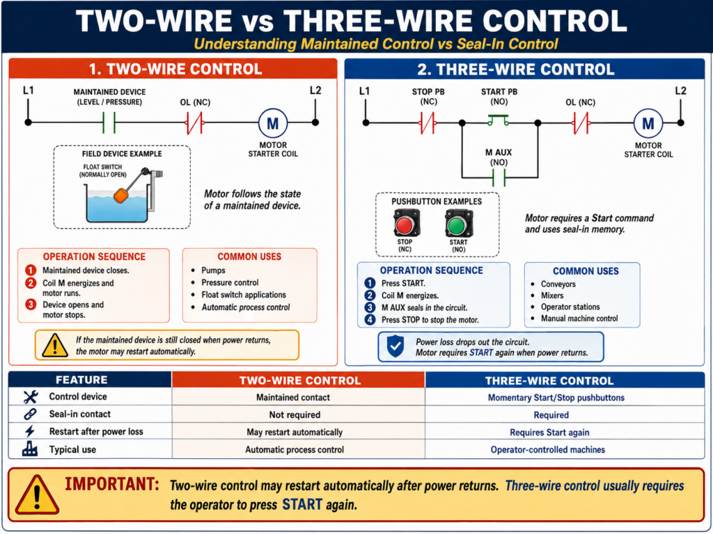
Introduction
In industrial motor control, two of the most common control methods are two-wire control and three-wire control.
Both methods can start and stop a motor, but they behave very differently. Understanding this difference is very important for automation technicians, especially when troubleshooting motor starters, pumps, conveyors, fans, and PLC-controlled systems.
A simple way to remember it is:
Two-wire control follows the state of a maintained device.
Three-wire control uses momentary Start/Stop pushbuttons with seal-in logic.
The difference matters because one circuit may automatically restart after power returns, while the other usually requires the operator to press Start again.
What Is Two-Wire Control?
Two-wire control uses a maintained contact device to start and stop the motor.
A maintained contact stays either open or closed until the physical device changes state. Common examples include:
- Float switch
- Pressure switch
- Limit switch
- Thermostat
- Selector switch
- Maintained ON/OFF switch
The MCTrainer lab material describes two-wire controls as devices with a definite ON or OFF position, and includes practical examples using float switches, pressure switches, limit switches, single pole switches, and foot switches to operate a motor starter.
Basic Two-Wire Control Circuit
A simple two-wire circuit may look like this:
L1 ----[ Float Switch ]----[/ OL ]----( M )
L2
Where:
[ Float Switch ] = Maintained control device
[/ OL ]          = Normally closed overload contact
( M )            = Motor starter coil
When the float switch closes, the motor starter coil energizes.
When the float switch opens, the motor starter coil de-energizes.
Two-Wire Control Sequence
Step 1 — Control Device Closes
Example: A tank level drops and the float switch closes.
Float switch closes → Starter coil energizes → Motor startsStep 2 — Motor Runs
The motor continues running as long as the maintained device remains closed.
Float switch remains closed → Motor keeps runningStep 3 — Control Device Opens
Example: The tank fills and the float switch opens.
Float switch opens → Starter coil de-energizes → Motor stopsThere is no Start pushbutton seal-in circuit required. The field device itself controls the motor state.
Common Two-Wire Control Applications
Two-wire control is common in automatic systems where the process device directly determines when the motor runs.
Examples:
| Application | Maintained Device | Motor Behavior |
|---|---|---|
| Sump pump | Float switch | Runs when level rises |
| Air compressor | Pressure switch | Runs when pressure is low |
| Exhaust fan | Thermostat | Runs when temperature is high |
| Conveyor permissive | Limit switch | Runs when switch condition is made |
| Simple transfer pump | Selector switch | Runs when switch is ON |
Two-wire control is simple and effective, but it must be applied carefully because of restart behavior.
Important Behavior: Automatic Restart
The biggest thing to understand about two-wire control is this:
If the maintained device is closed when power returns, the motor may restart automatically.
Example:
- A float switch is closed because the tank level is low.
- The pump motor is running.
- Facility power is lost.
- The starter drops out.
- Power returns.
- The float switch is still closed.
- The motor starts again automatically.
This behavior can be acceptable for some process applications, such as pumps or fans, but it may be unsafe for equipment where unexpected startup can injure someone.
What Is Three-Wire Control?
Three-wire control uses momentary Start and Stop pushbuttons with a seal-in auxiliary contact.
A typical three-wire control circuit includes:
- Normally closed Stop pushbutton
- Normally open Start pushbutton
- Motor starter coil
- Normally open auxiliary seal-in contact
- Normally closed overload contact
The MCTrainer material separates three-wire control as its own foundational unit and includes practical circuits for single Start/Stop stations, multiple Start/Stop stations, ON/OFF pilot lights, push-to-test lights, and alarm silencing.
Basic Three-Wire Control Circuit
L1 ----[/ STOP]----[ START ]----[/ OL ]----( M )
              |----[ M AUX ]----|
L2
Where:
[/ STOP]  = Normally closed Stop pushbutton
[ START ] = Normally open Start pushbutton
[/ OL ]   = Normally closed overload contact
( M )     = Motor starter coil
[ M AUX ] = Normally open auxiliary contact from motor starter
The Start button gives a momentary start command. The auxiliary contact seals in the circuit after the coil energizes.
Three-Wire Control Sequence
Step 1 — Operator Presses Start
Start PB closes → Starter coil energizes → Motor startsStep 2 — Auxiliary Contact Seals In
When the starter coil energizes, the auxiliary contact closes.
M Aux closes → Circuit stays energized after Start is releasedStep 3 — Motor Keeps Running
The motor continues to run through the seal-in contact.
Stop closed + Overload OK + M Aux closed = Motor continues runningStep 4 — Operator Presses Stop
Stop PB opens → Coil drops out → Motor stopsStep 5 — Power Loss
If control power is lost, the coil drops out and the auxiliary contact opens.
When power returns, the motor does not restart automatically. The operator must press Start again.
The motor control glossary defines low voltage protection as a three-wire control setup where, after voltage drops and is restored, the contactor remains open.
Two-Wire vs Three-Wire Control: Main Difference
| Feature | Two-Wire Control | Three-Wire Control |
|---|---|---|
| Control device | Maintained contact | Momentary pushbuttons |
| Typical devices | Float switch, pressure switch, selector switch | Start PB and Stop PB |
| Seal-in contact | Not required | Required |
| Operator Start required? | Not always | Yes |
| Restart after power loss | May restart automatically | Usually does not restart automatically |
| Common use | Automatic process control | Operator-controlled machines |
| Main risk | Unexpected restart | More wiring/logic required |
Why Three-Wire Control Is Common for Operator Stations
Three-wire control is very common when a human operator starts and stops a machine.
Examples:
- Conveyor Start/Stop station
- Mixer motor control
- Packaging machine motor
- Machine section enable
- Local motor starter
- Manual machine operation
This is because three-wire control provides low voltage protection. If power drops out, the operator must intentionally restart the motor.
That is usually safer for equipment where automatic restart could create a hazard.
Why Two-Wire Control Is Common for Pumps and Process Devices
Two-wire control is common when the process condition should automatically control the motor.
Examples:
- Pump starts when tank level rises
- Compressor starts when pressure drops
- Fan starts when temperature rises
- Pump stops when level reaches setpoint
In these cases, automatic restart may be expected.
However, the machine design must still consider safety, lockout/tagout, guarding, alarms, and process hazards.
Basic Troubleshooting: Two-Wire Control
When troubleshooting a two-wire control circuit, follow the maintained device.
Example circuit:
L1 ----[ Pressure Switch ]----[/ OL ]----( M )
L2
Ask:
- Is control voltage present?
- Is the pressure switch supposed to be open or closed?
- Is the pressure switch actually changing state?
- Is the overload contact closed?
- Is the starter coil receiving voltage?
- Is the contactor pulling in?
Common Two-Wire Problems
| Symptom | Possible Cause |
|---|---|
| Motor does not start | Maintained switch open, no control voltage, overload tripped |
| Motor never stops | Switch stuck closed, wrong pressure/level setting, wiring short |
| Motor restarts unexpectedly | Maintained device still closed when power returned |
| Motor chatters | Loose wire, unstable switch, weak coil, low control voltage |
Basic Troubleshooting: Three-Wire Control
When troubleshooting a three-wire circuit, follow the Start/Stop and seal-in path.
Example circuit:
L1 ----[/ STOP]----[ START ]----[/ OL ]----( M )
              |----[ M AUX ]----|
L2
Ask:
- Is the Stop button closed?
- Does the Start button close when pressed?
- Is the overload contact closed?
- Does the coil energize?
- Does the auxiliary contact close?
- Does the motor stay running after Start is released?
Common Three-Wire Problems
| Symptom | Possible Cause |
|---|---|
| Motor does not start | Stop open, Start failed, overload open, coil failed |
| Motor runs only while Start is pressed | Seal-in auxiliary contact not closing or wired wrong |
| Motor will not stop | Stop bypassed, contactor welded, incorrect wiring |
| Motor drops out randomly | Loose wire, low control voltage, overload contact opening |
Practical Technician Rule
Use this rule:
If the circuit uses a maintained device, think two-wire control.

If the circuit uses Start/Stop pushbuttons and an auxiliary holding contact, think three-wire control.
Another good rule:
Two-wire control remembers the position of the device.

Three-wire control remembers the run state through the seal-in contact.
PLC Version of Two-Wire Control
In PLC logic, two-wire control is often represented by a maintained input.
Example:
Pump_Run_Command = Level_Switch AND Overload_OK AND Safety_OKIf the level switch is ON, the pump runs.
If the level switch turns OFF, the pump stops.
This is simple automatic control.
PLC Version of Three-Wire Control
Three-wire control in PLC logic usually uses a seal-in or latch-style rung.
Example:
Motor_Run_Command =
    Stop_OK
    AND Overload_OK
    AND Safety_OK
    AND (Start_PB OR Motor_Run_Command)
This behaves like a hardwired seal-in circuit.
But in professional PLC logic, it is often better to structure the logic clearly:
Start_Request
Stop_Request
Permissives_OK
Motor_Run_Command
Motor_Output
Motor_Run_Feedback
Motor_Fault
A clean sequence is:
Request → Permissives → Command → Output → FeedbackThis makes the motor logic easier to troubleshoot and easier to expand with alarms and faults.
Command vs Feedback in Both Methods
Whether the motor is controlled by two-wire or three-wire logic, the same industrial concept applies:
Command is what the system wants.
Feedback is proof that the motor actually responded.
For example:
Motor_Run_Command = ON
Motor_Run_Feedback = OFF
This may indicate:
- Failed contactor coil
- Tripped overload
- VFD fault
- Blown fuse
- Bad auxiliary contact
- Broken feedback wire
- Motor not actually running
Good motor control logic should not only command the motor. It should also verify that the motor responds.
Safety Considerations
Two-wire and three-wire control circuits must be applied based on the risk of the machine.
Two-Wire Control Safety Concern
Two-wire control can restart automatically after power loss if the maintained device remains closed.
This may be acceptable for certain process equipment, but dangerous for operator-accessible machinery.
Three-Wire Control Safety Benefit
Three-wire control usually prevents automatic restart after power loss because the seal-in contact drops out when the coil loses power.
This is why three-wire Start/Stop control is common for operator-controlled machinery.
Important Safety Note
Safety circuits, E-Stops, guard doors, and life-safety functions should not depend only on standard PLC logic unless the system is specifically designed with safety-rated hardware and standards.
Industrial Examples
Example 1 — Two-Wire Pump Control
A sump pump uses a float switch.
Float High = Pump runs
Float Low = Pump stops
If power fails while the float is high, the pump will likely restart when power returns.
This may be desired because the sump still needs to be pumped down.
Example 2 — Three-Wire Conveyor Control
A conveyor uses Start and Stop pushbuttons.
Press Start = Conveyor runs
Press Stop = Conveyor stops
Power loss = Conveyor stops and requires restart
This is usually better for operator safety because the conveyor does not automatically restart when power returns.
Example 3 — PLC Controlled Mixer
A mixer may use three-wire style logic in the PLC.
Inputs:
Start_PB
Stop_PB
Overload_OK
Guard_Closed
Mixer_Run_FB
Internal bits:
Mixer_Start_Request
Mixer_Run_Command
Mixer_Failed_To_Start
Mixer_Overload_Fault
Output:
Mixer_Starter_OutputFeedback:
Mixer_Run_FBThis structure allows the PLC to control the motor and detect abnormal conditions.
Quick Comparison Summary
Two-Wire Control:
Maintained device controls the motor directly.
Simple automatic control.
May restart automatically after power returns.

Three-Wire Control:
Momentary Start/Stop uses seal-in logic.
Operator must intentionally start the motor.
Provides low voltage protection.
Final Thoughts
Two-wire and three-wire control are foundational concepts in industrial motor control.
Two-wire control is simple and useful for automatic process devices like float switches, pressure switches, and thermostats. The motor follows the state of the maintained device.
Three-wire control uses momentary Start and Stop pushbuttons with a seal-in auxiliary contact. It is commonly used for operator-controlled motors because it prevents automatic restart after power loss.
For automation technicians, understanding the difference is critical. It helps you troubleshoot motor starters, read ladder diagrams, understand PLC logic, and recognize when a circuit may restart automatically.
The key is not only knowing how to start a motor, but knowing how the motor behaves after a stop, overload, or power loss.