How to Troubleshoot PLC Inputs and Outputs
A Practical Guide for Automation Technicians
When a machine stops working, many people quickly say:
“The PLC is not working.”
But in real industrial troubleshooting, the PLC is only one part of the control system.
A machine problem can come from:
Sensor
Field wiring
Input module
PLC logic
Output module
Fuse
Relay
Solenoid
Motor starter
VFD
Pneumatic device
Mechanical condition
Safety circuit
That is why a good technician does not guess. A good technician follows the signal path.
The I/O section communicates with field devices by receiving input signals from devices such as limit switches and proximity sensors, and by sending output signals to devices such as motor starters, relays, and solenoids.
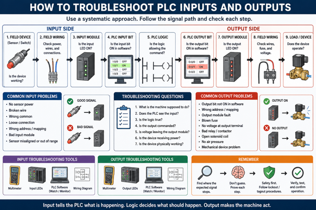
A simple troubleshooting mindset is:
Inputs tell the PLC what is happening.
Logic decides what should happen.
Outputs command the machine to act.
1. Start With the Basic Question
Before connecting to the PLC or replacing parts, ask:
What should be happening, and what is actually happening?
Example:
The conveyor should start when Start is pressed.
But the conveyor does not run.
Now separate the problem into sections:
Does the PLC see the input?
Is the logic allowing the command?
Is the PLC output turning ON?
Is the field device responding?
This prevents random troubleshooting.
2. The PLC I/O Troubleshooting Path
A clean troubleshooting path looks like this:
Field Device
     ↓
Field Wiring
     ↓
Input Module
     ↓
PLC Logic
     ↓
Output Module
     ↓
Field Wiring
     ↓
Load / Device
In practical terms:
Sensor → Input LED → PLC input bit → Logic conditions → Output bit → Output LED → Voltage → Device actionIf you follow this path, you can isolate where the problem is happening.
Part 1: Troubleshooting PLC Inputs
3. What Is a PLC Input Problem?
A PLC input problem happens when the real-world signal does not properly reach the PLC logic.
Example:
A sensor detects a box,
but the PLC input does not turn ON.
That problem could be caused by:
Bad sensor
No sensor power
Wrong sensor wiring
Broken cable
Loose terminal
Wrong common
Blown fuse
Bad input module
Wrong input address
Incorrect logic interpretation
The key is to prove where the signal is lost.
4. Input Troubleshooting Step-by-Step
Step 1: Check the field device physically
Look at the actual sensor, switch, or push button.
Ask:
Is the device powered?
Is the sensor LED changing state?
Is the push button mechanically working?
Is the limit switch being actuated?
Is the photoeye aligned?
Is the target actually present?
A photoeye may be misaligned.
A proximity sensor may not be close enough to the target.
A limit switch may not be mechanically actuated.
Never assume the device is working just because it is installed.
Step 2: Check power to the device
Many input devices need power.
Common sensor power:
24 VDC brown wire = positive
Blue wire = 0 VDC common
Black wire = signal output
Use a meter and verify:
24 VDC present at sensor
0 VDC common present
Signal wire changes state
A sensor cannot send a good signal if it does not have proper power.
Step 3: Check the input module LED
Most PLC input modules have status LEDs.
If the field device turns ON, the input LED should usually turn ON.
Example:
Sensor detects part
        ↓
Input terminal receives voltage
        ↓
Input LED turns ON
If the sensor LED is ON but the PLC input LED is OFF, the problem may be between the sensor and the input module.
Possible causes:
Broken wire
Wrong terminal
Loose connection
Wrong common
Incorrect sensor type
Blown input fuse
Bad module point
The answer key notes that if there is no voltage reading at the input module, the input device or field wiring may be the source of the problem.
Step 4: Check the input bit in the PLC software
The input LED may be ON, but you still need to verify the PLC logic sees the correct bit.
In the programming software, check:
Is the correct input address turning ON?
Is the correct tag changing state?
Is the input mapped correctly?
Is the logic using the correct input?
Example:
Physical input LED: ON
PLC tag DI_Box_Present: OFF
That could mean:
Wrong address
Bad mapping
Wrong alias tag
Wrong module slot
Incorrect input buffer logic
5. Input Problem Example
Symptom
The machine does not start when the Start button is pressed.Check path
Start push button physically pressed?
        ↓
24 VDC present?
        ↓
PLC input LED turns ON?
        ↓
DI_Start_PB tag turns ON?
        ↓
Logic sees Start request?
Possible findings
| Finding | Likely Problem |
|---|---|
| Button does not click properly | Bad push button |
| No 24 VDC at button | Power / fuse issue |
| Voltage changes at button but not module | Wiring issue |
| Input LED ON but tag OFF | Address or mapping issue |
| Tag ON but no run command | Logic / permissive issue |
This method isolates the problem instead of guessing.
6. Common PLC Input Problems
| Symptom | Possible Cause |
|---|---|
| Sensor LED ON, PLC input OFF | Wiring, common, input module, wrong terminal |
| PLC input ON all the time | Shorted wire, stuck sensor, wrong logic |
| Input flickers | Loose wire, sensor chatter, noise, poor alignment |
| Input never changes | Bad device, no power, wrong target, bad input point |
| Input works at device but not in logic | Wrong tag/address, input buffer issue |
| Input works sometimes | Intermittent wire, vibration, loose connector |
Part 2: Troubleshooting PLC Logic
7. When the Input Is Good but the Output Does Not Turn On
Sometimes the PLC sees the input correctly, but the machine still does not respond.
This is when you move to the logic.
Ask:
Is the correct mode selected?
Are safety conditions healthy?
Is an overload active?
Is a fault latched?
Is the sequence in the correct step?
Is a permissive missing?
Is a timer not done?
Is an interlock blocking the output?
This is where PLC troubleshooting becomes more than checking voltage.
8. Logic Troubleshooting Example
Symptom
Start_PB input turns ON,
but Motor_Run_Cmd does not turn ON.
Check the rung:
Stop_OK
Safety_OK
Overload_OK
No_Faults
Auto_Mode
Start_PB
If any condition is false, the command will not energize.
Example:
Start_PB = TRUE
Stop_OK = TRUE
Safety_OK = TRUE
Overload_OK = FALSE
No_Faults = TRUE
Auto_Mode = TRUE
Result:
Motor_Run_Cmd = FALSEThe problem is not the Start button.
The problem is the overload permissive.
9. Inputs, Permissives, Interlocks, and Faults
A common beginner mistake is thinking:
Start_PB ON = Motor ONIn real industrial logic, the Start button is only a request.
A better structure is:
Start Request
     ↓
Permissives healthy?
     ↓
Interlocks clear?
     ↓
No faults active?
     ↓
Mode allows operation?
     ↓
Run command turns ON
This is why an input can be working correctly but the output still does not energize.
Part 3: Troubleshooting PLC Outputs
10. What Is a PLC Output Problem?
A PLC output problem happens when the PLC command does not properly operate the field device.
Example:
PLC output is ON,
but the solenoid valve does not actuate.
That problem could be caused by:
Bad output module
Blown fuse
No load power
Bad relay
Bad solenoid coil
Loose wire
Broken common
Mechanical valve problem
No air pressure
Wrong output address
Logic not actually energizing output
The answer key explains that checking with a programming device can help determine whether the program logic is enabling the output.
11. Output Troubleshooting Step-by-Step
Step 1: Check if the PLC logic is commanding the output
In software, verify:
Is the output command bit ON?
Is the output buffer bit ON?
Is the physical output tag ON?
Example:
Motor_Run_Cmd = TRUE
DO_Motor_Starter = TRUE
If the command bit is OFF, do not troubleshoot the field device yet. Go back to the logic.
Step 2: Check the output module LED
If the output bit is ON, check the physical output module LED.
PLC output bit ON
        ↓
Output module LED should turn ON
If the software output is ON but the module LED is OFF, possible causes include:
Wrong output address
Module fault
Output not mapped correctly
Remote I/O issue
Program using internal bit only
Controller not in RUN mode
Step 3: Check voltage at the output terminal
If the output LED is ON, use a meter to verify voltage at the output terminal.
Ask:
Is voltage leaving the output module?
Is the correct common present?
Is the load supply available?
Is a fuse blown?
Is the output sourcing or sinking correctly?
An output LED can be ON, but the field device may still not receive usable voltage.
Step 4: Check interposing relay or contactor
Many PLC outputs do not drive the final load directly.
They may energize:
Interposing relay
Contactor coil
Motor starter coil
Solenoid coil
VFD digital input
If an interposing relay is used, check:
Is the relay coil energized?
Are relay contacts closing?
Is load voltage present at the relay contact?
Is the relay socket seated properly?
Is the relay damaged?
The answer key explains that an interposing relay is used to handle output loads larger than the PLC output can handle and to isolate the output device from the PLC.
Step 5: Check the field device
If voltage reaches the field device but it does not operate, the issue may be the device itself.
Examples:
Solenoid coil open
Valve stuck mechanically
No air pressure
Motor starter coil failed
Contactor mechanically stuck
VFD not ready
Alarm horn failed
Stack light lamp/LED failed
At this stage, the PLC may be doing its job correctly. The problem is outside the PLC.
12. Output Problem Example
Symptom
PLC commands a solenoid,
but the cylinder does not extend.
Check path
PLC output command ON?
        ↓
Output LED ON?
        ↓
Voltage at output terminal?
        ↓
Relay energized?
        ↓
Voltage at solenoid?
        ↓
Solenoid coil good?
        ↓
Air pressure available?
        ↓
Valve mechanically shifting?
        ↓
Cylinder mechanically free?
Possible findings
| Finding | Likely Problem |
|---|---|
| Output command OFF | Logic / permissive issue |
| Output LED OFF | Address, module, or mapping issue |
| No voltage at output terminal | Fuse, module, supply issue |
| Relay energizes but no voltage out | Bad relay contact |
| Solenoid has voltage but no movement | Bad coil, no air, stuck valve |
| Valve shifts but cylinder does not move | Pneumatic or mechanical issue |
This is how you separate PLC problems from field problems.
Part 4: Input vs Output Troubleshooting
13. Quick Comparison
| Area | Main Question | Common Tools |
|---|---|---|
| Input | Does the PLC see the field signal? | Meter, input LED, software tag |
| Logic | Is the program allowing the command? | PLC software, rung status |
| Output | Is the PLC commanding the device? | Output LED, software tag, meter |
| Field Device | Did the device actually operate? | Meter, mechanical check, air/power check |
Simple technician mindset:
Input side = information coming in
Logic side = decision being made
Output side = command going out
Field side = real action happening
14. The Best Troubleshooting Questions
Use these questions every time:
What is the machine supposed to do?
What condition is missing?
Does the PLC see the input?
Is the logic true?
Is the output commanded?
Is voltage leaving the output?
Is the device receiving power?
Is the device physically working?
This keeps troubleshooting structured.
15. Do Not Forget Safety Circuits
Many machines will not run because the safety circuit is not healthy.
Always check:
E-Stop released
Safety relay healthy
Guard doors closed
Light curtain clear
Safety reset completed
STO circuit healthy
Motor overload reset
VFD ready
Remember:
The PLC may monitor safety,
but the safety circuit should perform the actual stop function.
The answer key explains that a hardwired emergency stop circuit is recommended because it provides a redundant method of stopping output signals independent of the PLC program.
16. Input Buffer and Output Buffer Concept
A cleaner PLC program often separates raw I/O from internal logic.
Input Buffer
Raw input signal
        ↓
Clean internal tag
        ↓
Used in logic
Example:
Local:1:I.Data.0 → DI_Start_PBOutput Buffer
Internal command
        ↓
Physical output mapping
Example:
Motor_Run_Cmd → Local:2:O.Data.0This makes troubleshooting easier because you can separate:
Raw field signal
Clean PLC input tag
Internal command
Physical output
17. Recommended Tag Naming
Good tag names make troubleshooting faster.
Input tags
DI_Start_PB
DI_Stop_OK
DI_Safety_OK
DI_Box_PE
DI_Motor_OL_OK
DI_Motor_FB
Internal logic tags
Motor_Run_Request
Motor_Run_Cmd
Machine_Run_Permissive
No_Active_Faults
Box_Present
Output tags
DO_Motor_Starter
DO_Solenoid_Extend
DO_Green_Light
DO_Alarm_Horn
Fault tags
Fault_Motor_Overload
Fault_Motor_Feedback
Fault_Box_Jam
Fault_Safety_Circuit
This style makes the program much easier to read.
18. Common Beginner Mistakes
Mistake 1: Blaming the PLC too quickly
Many problems are sensors, wiring, fuses, relays, or field devices.
Mistake 2: Looking only at the HMI alarm
The HMI tells you what the system thinks happened. It does not always tell you the root cause.
Mistake 3: Not using a meter
PLC software is powerful, but electrical troubleshooting still needs voltage checks.
Mistake 4: Confusing command with feedback
A PLC may command a motor to run, but feedback confirms if it actually ran.
Motor_Run_Cmd = PLC command
Motor_FB = real-world confirmation
Mistake 5: Ignoring mechanical or pneumatic problems
Sometimes the output is working electrically, but the device is stuck or has no air supply.
Mistake 6: Not checking the common
Missing common wiring can make both input and output troubleshooting confusing.
19. Practical Example: Motor Will Not Start
Symptom
Operator presses Start, but motor does not run.Troubleshooting path
1. Does DI_Start_PB turn ON?
2. Is DI_Stop_OK true?
3. Is DI_Safety_OK true?
4. Is DI_Motor_OL_OK true?
5. Is the VFD ready or starter available?
6. Does Motor_Run_Cmd turn ON?
7. Does DO_Motor_Starter turn ON?
8. Does output LED turn ON?
9. Is voltage reaching the starter coil?
10. Does the starter pull in?
11. Does motor feedback turn ON?
Possible root causes
Bad Start button
Open Stop circuit
Safety relay not reset
Overload tripped
VFD faulted
Run command blocked by logic
Bad output fuse
Failed starter coil
No control voltage
Motor mechanical issue
This is a professional troubleshooting approach.
20. Practical Example: Sensor Not Detecting Product
Symptom
Product is present, but PLC does not detect it.Troubleshooting path
1. Is the sensor aligned?
2. Is the target within sensing range?
3. Is the sensor powered?
4. Does the sensor LED change?
5. Does the signal wire change voltage?
6. Does the PLC input LED turn ON?
7. Does the PLC input tag turn ON?
8. Is the logic using the correct tag?
9. Is debounce logic preventing the signal?
10. Is the sensor type correct for the application?
Possible root causes
Misaligned photoeye
Wrong sensing distance
Bad cable
No 24 VDC
Wrong sensor type
Dirty lens
Loose terminal
Wrong input address
Bad input point
21. Practical Example: Output ON but Device Does Not Move
Symptom
PLC output is ON, but actuator does not move.Troubleshooting path
1. Is output command ON in software?
2. Is output module LED ON?
3. Is voltage at the output terminal?
4. Is voltage reaching the solenoid?
5. Is the solenoid coil good?
6. Is air pressure available?
7. Is the valve shifting?
8. Is the cylinder mechanically stuck?
Possible root causes
Blown output fuse
Bad relay
Open solenoid coil
No air pressure
Stuck valve
Broken tubing
Mechanical jam
This shows why PLC troubleshooting must include electrical, pneumatic, and mechanical thinking.
22. Technician Checklist
Use this checklist when troubleshooting PLC I/O:
| Check | Input Side | Output Side |
|---|---|---|
| Field device | Sensor, switch, push button | Solenoid, relay, starter |
| Power | Sensor supply | Load supply |
| Common | Input common | Output common |
| Module LED | Input LED | Output LED |
| PLC tag | Input bit/tag | Output bit/tag |
| Logic | Permissive/interlock | Command/output buffer |
| Wiring | Signal wire | Load wire |
| Device action | Signal changes | Device actuates |
Final Thoughts
PLC input and output troubleshooting is about following the signal path.
Do not guess. Prove each step.
For inputs:
Field device → Wiring → Input module → PLC tag → LogicFor outputs:
Logic → Output tag → Output module → Wiring → Field deviceA good Automation Technician understands that the PLC is not the whole machine. The real problem can be in the field device, the wiring, the module, the logic, the output circuit, or the mechanical equipment.
The goal is simple:
Find where the expected signal stops.Once you find that point, the troubleshooting becomes much easier.