PLC Counters for Production Tracking
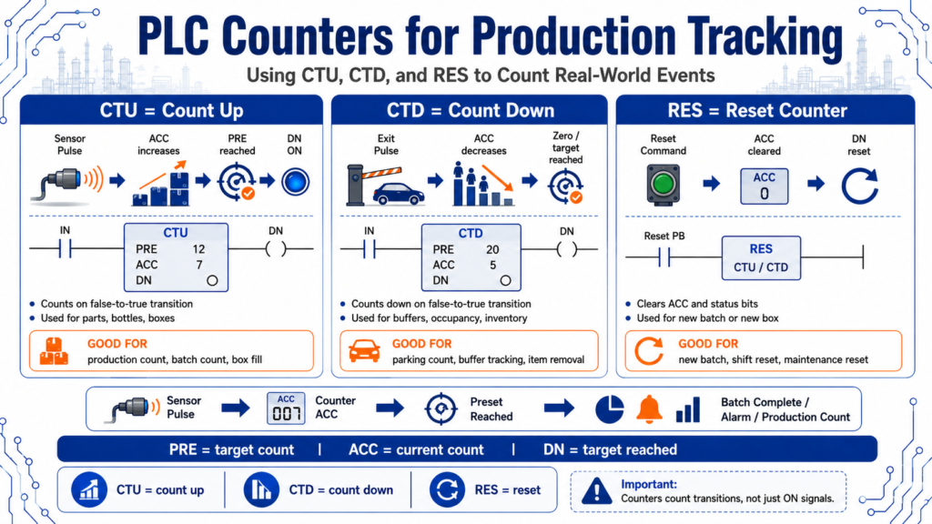
Using CTU, CTD, and RES to Count Real-World Events
Counters are one of the most useful instructions in PLC programming because industrial machines are constantly counting something.
A PLC may need to count:
Parts
Bottles
Boxes
Pulses
Cycles
Rejects
Good products
Bad products
Cars entering a parking garage
Flowmeter pulses
Machine starts
Maintenance cycles
In production environments, counters help turn machine activity into useful information.
They answer questions like:
How many parts were produced?
How many rejects occurred?
Has the batch reached the target quantity?
Is the box full?
How many cars are inside the garage?
How many cycles has this machine completed?
The PLCTrainer manual explains that programmed counters add flexibility and control for electrical process equipment and driven machinery. It also explains that counters store preset and accumulated values, and that counters increment or decrement when the count rung transitions from false to true.
That last point is very important:
Counters count transitions, not simply ON signals.
1. What Is a PLC Counter?
A PLC counter is an instruction that counts events.
The event is usually created by a sensor or command changing state.
Example:
Box sensor OFF → ON
        ↓
Counter increments by 1
The PLC does not count because the sensor is ON. It counts when the rung changes from false to true.
That means if a sensor stays ON, the counter should not keep counting every scan. It should count the transition.
Simple concept:
One clean pulse = one count2. Basic Counter Terms
Before using counters, it helps to understand the basic terms.
| Term | Meaning |
|---|---|
| CTU | Count Up instruction |
| CTD | Count Down instruction |
| RES | Reset instruction |
| PRE / Preset | Target count value |
| ACC / Accumulated | Current count value |
| DN / Done Bit | Turns on when the counter reaches the preset |
| CU Bit | Count Up status bit |
| CD Bit | Count Down status bit |
A simple way to remember it:
PRE = target count
ACC = current count
DN = target reached
Observe the counter’s accumulator, preset, and primary control bits, including CU, CD, and DN.
3. CTU — Count Up
A CTU instruction counts upward.
Each time the rung transitions from false to true, the counter accumulator increases by one.
Example:
Part_Sensor changes OFF → ON
        ↓
CTU increments ACC by 1
If the preset is 20, then when the accumulated count reaches 20, the done bit turns on.
C5:1.PRE = 20
C5:1.ACC = 20
C5:1/DN = TRUE
Increment as increasing in value, or counting up.
4. CTU Practical Example: Counting Boxes
Imagine a conveyor with a photoeye detecting boxes.
Box_Photoeye
      ↓
CTU Box_Count
      ↓
When Box_Count.ACC reaches 20
      ↓
Turn on Box_Full indicator
Simple logic concept:
Box_Detected_Pulse -------- CTU Box_Count
Box_Count.DN -------------- Box_Full_Light
Reset_PB ------------------ RES Box_Count
This is useful for:
Case packing
Box counting
Batch completion
Production totals
Palletizing
Reject counting
5. CTD — Count Down
A CTD instruction counts downward.
Each false-to-true transition causes the accumulated value to decrease.
Example:
Part_Removed_Sensor changes OFF → ON
        ↓
CTD decrements ACC by 1
The answer key defines decrement as decreasing in value, or counting down.
CTD instructions are useful when you need to subtract events from a total.
Examples:
Items leaving a buffer
Cars exiting a parking garage
Parts removed from a queue
Bottles rejected from production
Inventory decreasing
6. Using CTU and CTD Together
A powerful pattern is using a CTU and CTD together.
Example: parking garage count.
Car enters → CTU increments count
Car exits  → CTD decrements count
If the garage capacity is 300 cars:
Garage_Count.ACC >= 300
        ↓
Garage_Full_Light = ON
A practical exercise where a control system monitors cars entering and exiting a parking garage with 300 spaces; cars entering and exiting are detected by inductive proximity sensors.
This is a great real-world example because it shows that counters are not only for factory parts. They are useful anytime a process needs to track quantity.
7. RES — Reset Instruction
The RES instruction resets the counter.
A reset normally clears:
ACC value
DN bit
Counter status bits
Example:
Reset_Button -------- RES Box_CountThe PLCTrainer manual explains that using a RES instruction with the same counter address resets the accumulated value and control bits when the reset instruction is enabled.
A reset is commonly used when:
A new batch starts
The operator clears a count
A full box is removed
A pallet is replaced
Maintenance resets cycle count
A shift total is cleared
8. Important: Counters Can Count Past the Preset
One important beginner concept:
A counter can continue counting beyond its preset.
The done bit turns on when the accumulated value reaches the preset, but the accumulated value may continue increasing if additional count pulses occur.
The PLCTrainer manual explains that each count is retained when rung conditions become false, allowing counting to continue beyond the preset. This allows an output to be based on the preset while still tracking inventory or parts.
Example:
PRE = 20
ACC = 20
DN = TRUE

More parts pass...
ACC = 21
ACC = 22
ACC = 23
DN still TRUE
This can be useful, but it can also cause problems if the program expects the count to stop automatically.
9. Production Tracking Example
Imagine a simple production line.
Inputs
Good_Part_PE
Reject_PE
Reset_Shift_Count
Counters
Good_Parts_Count
Reject_Count
Total_Parts_Count
Outputs / Status
Batch_Complete
Reject_Limit_Alarm
Shift_Total_Display
Example logic:
Good_Part_Pulse -------- CTU Good_Parts_Count
Reject_Pulse ----------- CTU Reject_Count
Any_Part_Pulse --------- CTU Total_Parts_Count

Good_Parts_Count.DN ---- Batch_Complete
Reject_Count.DN -------- Reject_Limit_Alarm
Reset_Shift_Count ------ RES Good_Parts_Count
Reset_Shift_Count ------ RES Reject_Count
Reset_Shift_Count ------ RES Total_Parts_Count
This turns simple sensor pulses into production data.
10. Why Clean Pulses Matter
Counters depend on clean transitions.
If a sensor chatters, the counter may count too many times.
Example:
One box passes sensor
Sensor chatters ON/OFF quickly
Counter counts 3 or 4 times
That is why counters often need:
Debounce logic
One-shot logic
Pulse conditioning
Sensor alignment
Stable mounting
Correct scan time
The PLCTrainer manual notes that the counter’s ability to detect false-to-true transitions depends on the speed of the incoming signal, and that the ON and OFF duration of the signal must not be faster than the scan time.
That connects directly with the scan cycle topic from the previous post.
11. One-Shots With Counters
A one-shot is often used to make sure the counter only increments once per event.
Example:
Part_Sensor
      ↓
One-Shot
      ↓
CTU Part_Count
Why?
Because we want:
One part = one countNot:
One part sitting in front of sensor = repeated countsMost counters already count false-to-true transitions, but in real programs, a one-shot can make the intent clearer and help when the signal is used in multiple places.
12. Practical Example: Box Fill Count
Imagine a packaging machine filling a box with 12 bottles.
Bottle_Detected_Pulse -------- CTU Bottle_Count
Bottle_Count.PRE = 12
Bottle_Count.DN -------------- Box_Full
Box_Removed ------------------ RES Bottle_Count
Sequence:
1 bottle counted
2 bottles counted
3 bottles counted
...
12 bottles counted
Box_Full turns ON
Operator or machine removes box
Counter resets
Next box starts
This is a common production tracking pattern.
13. Practical Example: Reject Limit Alarm
Counters are also useful for quality monitoring.
Example:
Reject_Detected_Pulse -------- CTU Reject_Count
Reject_Count.PRE = 5
Reject_Count.DN -------------- Reject_Limit_Alarm
In plain English:
If 5 rejects occur during the batch,
turn on an alarm and alert the operator.
This can help identify machine problems before too many bad parts are produced.
14. Practical Example: Maintenance Cycle Count
Counters can also track machine usage.
Example:
Machine_Cycle_Complete_Pulse ---- CTU Cycle_Count
Cycle_Count.PRE = 10000
Cycle_Count.DN ------------------ Maintenance_Due
Maintenance_Reset_PB ------------ RES Cycle_Count
This is useful for:
Lubrication intervals
Filter replacement
Machine inspections
Tooling replacement
Preventive maintenance
This is a good example of how PLC data can support maintenance planning.
15. CTU / CTD Buffer Example
Some systems need to know how many parts are currently inside a machine zone.
Example:
Part_Entered_Zone_Pulse ---- CTU Zone_Count
Part_Exited_Zone_Pulse ----- CTD Zone_Count
If the zone should only hold 5 parts:
Zone_Count.ACC >= 5
        ↓
Zone_Full = TRUE
This logic can support:
Accumulation conveyors
Buffer tables
Indexing systems
Parking garage logic
In-process part tracking
16. Suggested Tag Names
Good tag names make counter logic easier to understand.
Input / pulse tags
PE_Part_Detected
ONS_Part_Detected
Part_Count_Pulse
Reject_Count_Pulse
Box_Removed_Pulse
Counter tags
CTR_Good_Parts
CTR_Rejects
CTR_Total_Parts
CTR_Box_Bottles
CTR_Machine_Cycles
CTR_Garage_Occupancy
Status tags
Batch_Complete
Box_Full
Reject_Limit_Reached
Garage_Full
Maintenance_Due
Reset tags
Reset_Batch_Count
Reset_Shift_Count
Reset_Box_Count
Reset_Maintenance_Count
Good naming helps both programming and troubleshooting.
17. Troubleshooting PLC Counters
When a counter does not work correctly, ask:
| Question | Why It Matters |
|---|---|
| Is the count signal changing from false to true? | Counters count transitions |
| Is the sensor chattering? | Chatter can cause extra counts |
| Is the pulse too fast? | PLC may miss the count |
| Is the ACC increasing or decreasing? | Confirms CTU or CTD behavior |
| Is the preset correct? | Wrong PRE causes wrong done point |
| Is the DN bit being used correctly? | DN controls batch/full logic |
| Is RES active? | Reset may clear the count unexpectedly |
| Is the same counter address reused? | Address conflicts cause confusing behavior |
| Is the routine being scanned? | Counter logic must execute |
| Does the process need one-shot logic? | Helps create clean count pulses |
This checklist is very useful in real plant troubleshooting.
18. Common Beginner Mistakes
Mistake 1: Thinking the counter counts every scan
A counter counts the transition, not every scan while the rung is true.
Mistake 2: Forgetting to reset the counter
If you never reset the counter, old counts may affect the next batch.
Mistake 3: Resetting the counter too early
If reset logic turns on before the count is used, the done bit may never be seen.
Mistake 4: Ignoring sensor bounce
One physical part may create multiple pulses if the sensor is unstable.
Mistake 5: Using the wrong preset
A preset of 10 when the box needs 12 parts will complete the batch too early.
Mistake 6: Not considering scan time
Fast pulses may be missed if the PLC cannot see the signal long enough.
Final Thoughts
PLC counters are simple, but they are extremely powerful.
They allow a PLC to track real-world events such as parts, boxes, cars, rejects, cycles, and production totals.
The three key instructions are:
CTU = Count Up
CTD = Count Down
RES = Reset
The most important idea is:
One clean transition = one countOnce you understand PRE, ACC, DN, and reset behavior, counters become a practical tool for production tracking, batching, quality monitoring, and maintenance planning.
For an Automation Technician, counters are more than a programming instruction. They are a way to turn machine events into useful information.