Analog Scaling Basics for PLC Technicians
Turning Real-World Signals Into Useful Numbers
In PLC troubleshooting and programming, not every signal is simply ON or OFF.
Many devices send a variable signal that represents a real-world measurement, such as:
Temperature
Pressure
Level
Flow
Weight
Valve position
Speed reference
Tank level
These are called analog signals.
Analog inputs and outputs are essential in many PLC-managed processes, and that a competent technician should understand how analog modules and their associated instructions work.
For a PLC technician, analog scaling is important because the PLC does not automatically “know” what 12 mA, 5 VDC, or 16384 raw counts means.
We have to convert the raw signal into a useful engineering value.
That process is called scaling.
1. Discrete vs Analog Signals
A discrete signal has only two states:
ON / OFF
TRUE / FALSE
1 / 0
Examples:
Start push button
Limit switch
Proximity sensor
Photoeye
Motor overload contact
Safety relay status
An analog signal represents a range of values.
Examples:
4–20 mA pressure transmitter
0–10 VDC level sensor
RTD temperature input
Load cell weight signal
Analog valve command
VFD speed reference
Analog value is continuous rather than discrete, and it lists examples of analog inputs such as oven temperature, valve position, and fluid pressure.
A simple way to remember it:
Discrete = ON or OFF
Analog = variable measurement
2. Why Scaling Is Needed
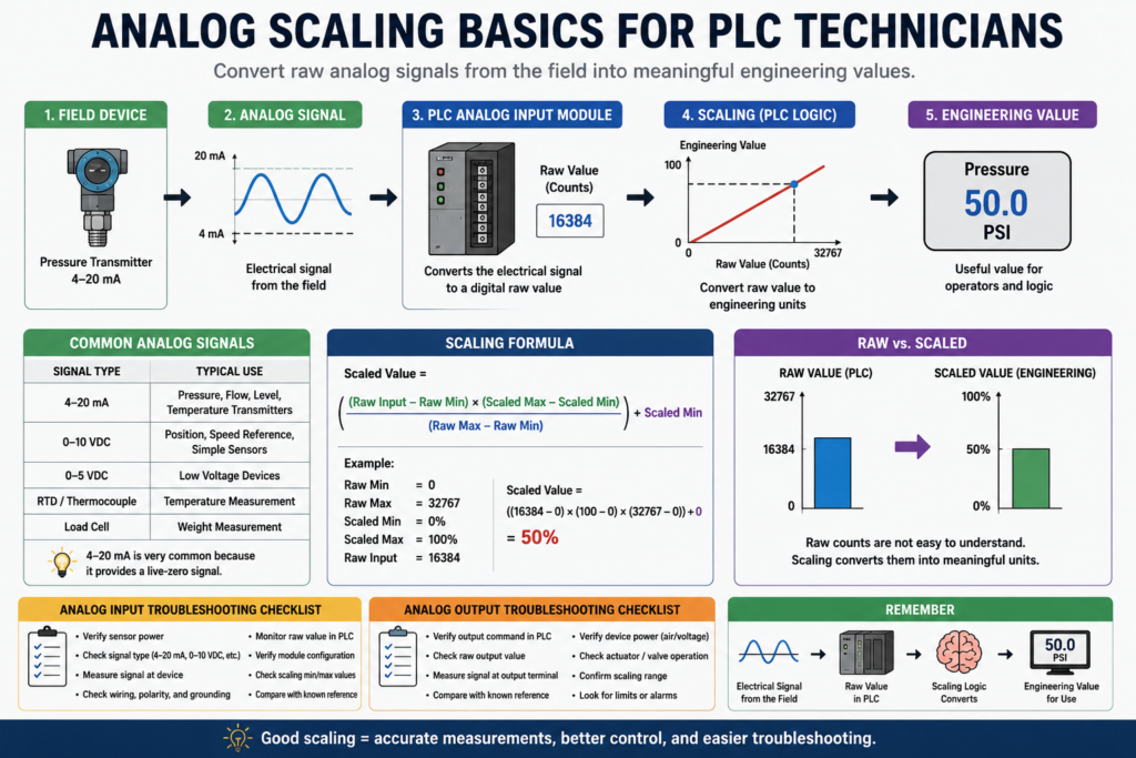
A PLC analog module converts an electrical signal into a number.
For example:
0–10 VDC signal → raw PLC counts
4–20 mA signal → raw PLC counts
But raw counts are not friendly for technicians or operators.
An operator does not want to see:
Raw value = 16384They want to see:
Tank Level = 50%
Pressure = 75 PSI
Temperature = 420°F
Weight = 8.0 lb
Scaling converts the raw number into an engineering unit.
Basic idea:
Raw Input Value → Scaling Logic → Engineering ValueExample:
Raw analog input = 16384
Scaled value = 50%
3. Common Analog Signal Types
The most common analog signals in industrial automation are:
| Signal Type | Common Use |
|---|---|
| 4–20 mA | Pressure, flow, level, temperature transmitters |
| 0–10 VDC | Potentiometers, speed reference, simple sensors |
| 0–5 VDC | Low-voltage analog devices |
| 1–5 VDC | Some process transmitters |
| RTD / Thermocouple | Temperature measurement |
| Load cell signal | Weight measurement through amplifier or scale module |
In the field, 4–20 mA is very common because it works well over long cable runs and provides a live-zero signal.
A 4 mA signal usually represents the low end of the range, not zero power.
Example:
4 mA  = 0 PSI
20 mA = 100 PSI
4. What Are Raw Counts?
Raw counts are the digital numbers created by the analog input module.
Depending on the PLC and module configuration, the raw range may be something like:
0 to 32767
0 to 16383
4000 to 20000
6242 to 31208
-32768 to 32767
The exact range depends on the PLC platform, analog module, signal type, and module configuration.
For beginner learning, a simple example is:
0 raw counts     = 0%
32767 raw counts = 100%
Scaling example where a proportional valve is scaled from 0 to 100 using an input range of 0 to 32767. It calculates the rate as (100 - 0) / (32767 - 0), which equals approximately 0.00305.
5. The Basic Scaling Formula
The most common scaling formula is:
Scaled Value =
((Raw Input - Raw Min) × (Scaled Max - Scaled Min) / (Raw Max - Raw Min)) + Scaled Min
In plain English:
Take the raw input.
Subtract the raw minimum.
Compare it to the raw range.
Multiply it by the engineering range.
Add the engineering minimum.
Example:
Raw Min = 0
Raw Max = 32767
Scaled Min = 0%
Scaled Max = 100%
Raw Input = 16384
Result:
Scaled Value ≈ 50%6. Simple Scaling Example: 0–10 VDC to 0–100%
Imagine a potentiometer sends a 0–10 VDC signal to an analog input module.
The PLC reads:
0 VDC  = 0 raw counts
10 VDC = 32767 raw counts
We want:
0 raw counts     = 0%
32767 raw counts = 100%
If the PLC raw value is 16384:
Scaled Value =
((16384 - 0) × (100 - 0) / (32767 - 0)) + 0

Scaled Value ≈ 50%
So the operator display should show:
Valve Command = 50%7. Simple Scaling Example: 4–20 mA to 0–100 PSI
Now imagine a pressure transmitter.
4 mA  = 0 PSI
20 mA = 100 PSI
The PLC module may convert the signal into raw counts.
For a simple example:
Raw Min = 4000
Raw Max = 20000
Scaled Min = 0 PSI
Scaled Max = 100 PSI
If the raw input is 12000:
Scaled Value =
((12000 - 4000) × (100 - 0) / (20000 - 4000)) + 0

Scaled Value =
(8000 × 100 / 16000)

Scaled Value = 50 PSI
So:
Raw 12000 = 50 PSIThis is why knowing the module’s raw range is critical.
8. Engineering Units
Engineering units are the real-world units that people understand.
Examples:
| Process | Engineering Unit |
|---|---|
| Pressure | PSI, bar, kPa |
| Temperature | °F, °C |
| Flow | GPM, LPM |
| Level | %, gallons, liters |
| Weight | lb, kg |
| Speed | RPM, Hz, % |
| Valve position | % open |
Good PLC programs do not leave analog values as raw counts only.
A better structure is:
AI_Tank_Level_Raw
AI_Tank_Level_Pct
AI_Tank_Level_Gallons
This makes logic and HMI displays much easier to understand.
9. Analog Input vs Analog Output
Analog inputs and analog outputs are different.
Analog Input
The PLC receives a variable signal from the field.
Example:
Pressure transmitter → PLC analog input → Pressure_PSIAnalog Output
The PLC sends a variable command to a field device.
Example:
PLC analog output → Control valve → Valve positionAnalog outputs such as fluid valve position, motor position, and flow rate.
In simple words:
Analog input = measurement coming in
Analog output = variable command going out
10. Analog Output Example: Valve Position
Imagine the PLC controls a proportional valve.
The operator enters:
Valve_Setpoint = 75%The PLC must convert 75% into the correct analog output signal.
Example:
0%   = 4 mA
100% = 20 mA
75%  = 16 mA
The valve receives the analog signal and moves to approximately 75% open.
This is why analog outputs also need scaling, limiting, and validation.
11. Scaling With SCP or SCL
In older Allen-Bradley systems, technicians may see instructions like:
SCP = Scale with Parameters
SCL = Scale
These instructions help convert raw analog values into engineering units.
The Lab Manual includes practical analog scenarios using SCL for a proportional valve and SCP for temperature control of a gas-fired oven.
In newer tag-based systems, scaling may be done in:
Module configuration
CPT instruction
Structured Text
Add-On Instruction
Function Block
HMI expression
Regardless of the method, the goal is the same:
Convert raw signal into useful engineering value.12. Example: Gas Oven Temperature Control
Scenario where an SCP instruction is used to control the temperature of a gas-fired oven between 400°F and 480°F. In that example, the gas valve is discrete, opening below 401°F and closing near 479°F, while the temperature must also be displayed on a digital readout.
This example shows something important:
An analog input can be used to control a discrete output.
Example:
Temperature analog input
        ↓
Scaled temperature in °F
        ↓
If temperature < 401°F
        ↓
Open gas valve
The input is analog, but the valve command can still be ON/OFF.
13. Example: Weight-Based Filling
Scenario where a conveyor moves a container under a fill hopper, and a transducer measures the combined weight of the container and material. The hopper closes when the total weight reaches 8 pounds, and the system tracks total processed weight for shipment.
This is a very practical example for technicians.
Analog weight signal:
Load cell / scale signal
        ↓
Analog module or scale controller
        ↓
Scaled weight value
        ↓
PLC closes hopper at target weight
This type of logic is common in:
Batching
Filling
Weighing
Packaging
Ingredient dosing
Tank loading
14. Analog Signal Noise
Analog inputs are more sensitive than simple digital inputs.
Noise can cause the value to jump or fluctuate.
Analog inputs are very sensitive to noise.
Common noise sources include:
VFD motor leads
Poor grounding
Long cable runs
Improper shielding
Loose terminals
Bad analog commons
EMI from contactors or solenoids
Power cables near signal cables
Symptoms of analog noise:
Pressure jumps randomly
Level reading flickers
Temperature value is unstable
Weight reading drifts
Valve command oscillates
HMI value keeps bouncing
15. Analog Troubleshooting Checklist
When troubleshooting analog signals, check:
| Check | Why It Matters |
|---|---|
| Sensor power | Transmitter needs proper supply |
| Signal type | 4–20 mA vs 0–10 VDC must match module setup |
| Raw value | Confirms PLC is receiving signal |
| Scaled value | Confirms math/configuration is correct |
| Wiring polarity | Wrong polarity can break current loop |
| Shielding | Reduces noise |
| Grounding | Prevents unstable readings |
| Module configuration | Wrong range causes wrong values |
| Engineering range | Wrong min/max causes wrong display |
| Sensor calibration | Field device may be out of calibration |
16. Common Analog Problems
| Symptom | Possible Cause |
|---|---|
| Raw value stuck at zero | No power, open loop, bad transmitter |
| Raw value maximum | Short, overrange, wrong wiring |
| Value jumps around | Noise, grounding, shielding, loose wire |
| Value is scaled wrong | Wrong raw min/max or engineering range |
| HMI shows wrong unit | HMI scaling or tag issue |
| 4 mA does not equal zero | Live-zero scaling not configured correctly |
| Output valve not moving | Analog output, valve power, air supply, actuator issue |
| Reading drifts slowly | Sensor calibration or process issue |
17. 4–20 mA Troubleshooting Basics
For a 4–20 mA loop:
4 mA should usually represent the low end.
20 mA should usually represent the high end.
Example:
4 mA  = 0 PSI
20 mA = 100 PSI
12 mA = 50 PSI
Useful checks:
Measure loop current
Verify transmitter power
Check loop polarity
Confirm module input type
Confirm shield termination
Verify scaling range
Compare local display to PLC value
A 4–20 mA loop is powerful because 0 mA usually indicates a problem, not a valid zero reading.
18. 0–10 VDC Troubleshooting Basics
For a 0–10 VDC signal:
0 VDC  = low end
10 VDC = high end
5 VDC  = midpoint
Example:
0 VDC  = 0%
10 VDC = 100%
5 VDC  = 50%
Useful checks:
Measure voltage at device
Measure voltage at module
Check common reference
Verify signal polarity
Check cable length/noise
Confirm module range
Verify scaling math
Voltage signals can be more sensitive to voltage drop and noise over long distances.
19. Scaling Mistakes Beginners Make
Mistake 1: Scaling 4–20 mA as if it were 0–20 mA
This causes the low end to be wrong.
Mistake 2: Not checking raw counts
Always check the raw value before blaming the scaling math.
Mistake 3: Using the wrong engineering range
Example:
Transmitter range = 0–300 PSI
PLC scaling = 0–100 PSI
The display will be wrong.
Mistake 4: Scaling in two places
If the module, PLC, and HMI all scale the same value, the final reading may be incorrect.
Mistake 5: Ignoring noise
Analog values that jump around may need wiring, shielding, grounding, filtering, or sensor checks.
Mistake 6: Forgetting limits
Analog values should often be clamped or validated.
Example:
If Scaled_Pressure < 0 then set to 0
If Scaled_Pressure > 100 then set to 100
20. Recommended Tag Names
Good tag names make analog logic much easier to read.
Raw input tags
AI_Tank_Level_Raw
AI_Pressure_Raw
AI_Temperature_Raw
AI_Weight_Raw
Scaled engineering tags
Tank_Level_Pct
Pressure_PSI
Temperature_F
Weight_LB
Flow_GPM
Analog output tags
AO_Valve_Command_Raw
Valve_Command_Pct
AO_VFD_Speed_Ref
VFD_Speed_Ref_Hz
Fault/status tags
Pressure_AI_Fault
Temperature_Out_Of_Range
Weight_Unstable
Analog_Signal_Loss
Valve_Command_Limited
A good structure is:
Raw value
Scaled value
Validated value
HMI value
Fault status
21. Practical PLC Technician Workflow
When working on analog scaling, follow this order:
1. Identify the field device range.
2. Identify the signal type.
3. Confirm the analog module configuration.
4. Monitor the raw PLC value.
5. Apply the correct scaling formula.
6. Compare scaled value to a known reference.
7. Verify the HMI display.
8. Test low, midpoint, and high values.
9. Check alarms and limits.
10. Document the scaling.
This method prevents guessing.
22. Technician Example: Pressure Transmitter
Device information
Pressure transmitter range: 0–150 PSI
Signal: 4–20 mA
PLC raw range: 4000–20000
Scaling
Raw Min = 4000
Raw Max = 20000
Engineering Min = 0 PSI
Engineering Max = 150 PSI
Expected values
| Signal | Raw Value | Scaled Value |
|---|---|---|
| 4 mA | 4000 | 0 PSI |
| 12 mA | 12000 | 75 PSI |
| 20 mA | 20000 | 150 PSI |
If the HMI shows 50 PSI when the transmitter local display shows 75 PSI, the scaling range may be wrong.
23. Technician Example: Tank Level
Device information
Level transmitter: 0–100%
Signal: 4–20 mA
PLC scaled tag: Tank_Level_Pct
Logic use
If Tank_Level_Pct >= 90
    High_Level_Alarm = TRUE

If Tank_Level_Pct <= 10
    Low_Level_Alarm = TRUE
Troubleshooting
If tank level is physically half full but the HMI shows 10%, check:
Raw value
Transmitter range
Module configuration
Scaling formula
HMI tag
Wiring and loop current
24. Technician Example: Analog Valve Output
Operator setpoint
Valve_Command_Pct = 60%Analog output
60% command = analog output signal to valvePossible checks:
Is the PLC command 60%?
Is the analog output raw value changing?
Is the output signal measured at the terminal?
Is the valve position feedback moving?
Is instrument air available?
Is the valve calibrated?
Do not assume an analog output problem is always a PLC issue. The valve, actuator, I/P converter, air supply, or mechanical linkage may be the real issue.
Final Thoughts
Analog scaling is one of the most important skills for PLC technicians because it connects electrical signals to real process values.
The basic idea is simple:
Electrical Signal → Raw PLC Value → Scaled Engineering Unit → Control DecisionA PLC cannot directly understand pressure, temperature, weight, or level. It only receives numbers. Scaling turns those numbers into values that operators and technicians can use.
For beginners, remember:
Discrete signals are ON/OFF.
Analog signals are variable.
Raw counts must be scaled.
Always verify the field signal, module setup, raw value, and engineering range.
Once you understand analog scaling, troubleshooting transmitters, analog modules, valves, VFD references, and process values becomes much easier.