Advanced PLC Logic Structure: State Machines
Building Professional and Industrial Ladder Logic with State Machines, Subroutines, and Status Codes
In a basic PLC program, it is common to organize the logic using a simple structure:
Input Buffering
Mode Selection
Requests
Permissives
Interlocks
Commands
Fault Logic
Alarm Logic
Output Buffering
HMI Status Bits
This is a very good foundation. It helps separate field inputs, operator requests, machine conditions, outputs, faults, alarms, and HMI information.
However, when a machine becomes more complex, this basic structure may not be enough by itself.
For example, if the machine has an automatic sequence, multiple steps, timers, feedback devices, recovery conditions, or fault handling, the program can become difficult to troubleshoot if the logic is spread across many unrelated rungs.
That is where a more advanced and professional structure becomes useful.
A more industrial PLC program should not only answer:
Can I turn this output ON?It should also answer:
What state is the machine in?
Why is it in that state?
What condition allows it to move to the next state?
What condition stops the sequence?
What status should be reported to the HMI?
What fault or alarm explains the problem?
This post explains a more advanced approach to PLC ladder logic structure using:
State Machines
Transition Logic
Command Mapping
Subroutine Status Codes
AOI Status Codes
Fault and Alarm Separation
HMI Diagnostic Status
1. From Basic Ladder Logic to Professional Sequence Logic
A simple ladder program usually works like this:
Start Button + Permissives + No Faults = Motor CommandThat is acceptable for basic motor control.
But for a real industrial sequence, the logic may need to control several steps.
Example:
Start sequence
Open valve
Wait for feedback
Start pump
Monitor flow
Fill tank
Stop pump
Close valve
Confirm complete
If each condition is written separately without a clear structure, troubleshooting becomes difficult.
The technician may ask:
Why did the sequence stop?
What step is active?
What condition is missing?
Did the machine fail, or is it just waiting?
Is the output off because of a fault, permissive, interlock, or mode issue?
A professional PLC program should make those answers easy to find.
2. What Is a State Machine in PLC Logic?
A state machine is a structured way to control a sequence using defined machine states.
Instead of having many random bits controlling the sequence, the PLC uses one main tag to identify the current step or state.
Example:
Machine_State = 0    IDLE
Machine_State = 10   READY
Machine_State = 20   STARTING
Machine_State = 30   RUNNING
Machine_State = 40   COMPLETE
Machine_State = 90   FAULTED
Only one main state should be active at a time.
This makes the sequence easier to understand because the technician can immediately see where the machine is.
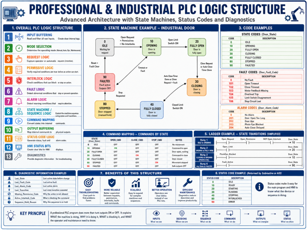
3. Simple Example: Industrial Door State Machine
For an industrial door, the states may look like this:
Door_State = 0     IDLE
Door_State = 10    OPENING
Door_State = 20    FULLY_OPEN
Door_State = 30    CLOSING
Door_State = 40    FULLY_CLOSED
Door_State = 90    FAULTED
Now the logic becomes much easier to follow.
Instead of asking:
Why is the open output on?
Why is the close output off?
Why did the auto-close not happen?
You can look at:
Door_StateIf the value is 30, the door is in the CLOSING state.
If the value is 90, the door is faulted.
If the value is 20, the door is fully open and may be waiting for the auto-close timer.
4. Why State Machines Are More Industrial
A state machine is useful because it separates the sequence into clear sections:
Current State
Transition Conditions
Commands by State
Faults by State
HMI Status by State
This is much cleaner than having sequence logic scattered everywhere.
In industrial troubleshooting, this matters a lot.
A good state machine tells the technician:
Where the machine is
What it is trying to do
What it is waiting for
What condition failed
What should happen next
That is exactly what maintenance needs during downtime.
5. Keep Transitions in One Place
One important recommendation is:
Keep all state transitions in one place.A transition is the condition that moves the sequence from one state to another.
Example:
IDLE → OPENING
OPENING → FULLY_OPEN
FULLY_OPEN → CLOSING
CLOSING → FULLY_CLOSED
ANY STATE → FAULTED
The transition logic should be grouped together in one routine or one clearly labeled section.
Recommended routine name:
Sequence_Transitionsor:
State_Machine6. Example: Door Transition Logic
IDLE to OPENING
IF Door_State = IDLE
AND Open_Request
AND Open_Permissive
AND No_Open_Interlock
THEN Door_State = OPENING
OPENING to FULLY_OPEN
IF Door_State = OPENING
AND DI_LS_Open_Position
THEN Door_State = FULLY_OPEN
FULLY_OPEN to CLOSING
IF Door_State = FULLY_OPEN
AND AutoClose_Timer.DN
AND NOT Manual_Stop_Latched
AND Close_Permissive
THEN Door_State = CLOSING
CLOSING to FULLY_CLOSED
IF Door_State = CLOSING
AND DI_LS_Closed_Position
THEN Door_State = FULLY_CLOSED
CLOSING to OPENING
IF Door_State = CLOSING
AND PhotoEye_Blocked
THEN Door_State = OPENING
This is a common industrial behavior for automatic doors. If the photo eye is blocked while closing, the door should stop closing and reopen.
ANY STATE to FAULTED
IF Fault_Active
THEN Door_State = FAULTED
This makes fault handling consistent.
7. Commands Should Be Based on State
In a professional structure, outputs should not be directly controlled by pushbuttons or random logic.
Instead, commands should be generated based on the current state.
Example:
Door_State = OPENING  → Open_Cmd = ON
Door_State = CLOSING  → Close_Cmd = ON
Door_State = FAULTED  → Open_Cmd = OFF and Close_Cmd = OFF
This is much cleaner.
Example Command Mapping
IF Door_State = OPENING
THEN Open_Cmd = ON
IF Door_State = CLOSING
THEN Close_Cmd = ONIF Door_State = FAULTED
THEN Open_Cmd = OFF
AND Close_Cmd = OFFThe state machine decides what the machine is doing.
The command logic converts that state into internal commands.
The output buffer maps those commands to real outputs.
8. Advanced Professional Structure
A more advanced industrial PLC structure may look like this:
1. Input Buffering
2. Mode Selection
3. Request Logic
4. Permissive Logic
5. Interlock Logic
6. Fault Detection
7. Alarm Detection
8. State Machine / Sequence Logic
9. Command Mapping
10. Output Buffering
11. Status Code Logic
12. HMI Status Bits
13. Diagnostics
This structure gives each part of the program a clear job.
9. What Each Section Does
1. Input Buffering
This routine cleans and standardizes field inputs.
Examples:
DI_Start_PB
DI_Stop_OK
DI_Motor_FB
DI_LS_Open
DI_LS_Closed
DI_PhotoEye_Clear
DI_Overload_OK
The rest of the program should use these internal tags instead of raw input addresses.
2. Mode Selection
This routine determines the operating mode.
Examples:
Mode_Manual
Mode_Auto
Mode_Off
Mode_Maintenance
Mode selection should be calculated before requests and sequence logic.
3. Request Logic
This routine captures operator or automatic intentions.
Examples:
Open_Request
Close_Request
Start_Request
Stop_Request
AutoClose_Request
Cycle_Start_Request
A request means:
Something wants an action to happen.It does not mean the output should energize immediately.
4. Permissive Logic
This routine determines whether the action is allowed to start.
Examples:
Open_Permissive
Close_Permissive
Motor_Start_Permissive
Pump_Start_Permissive
A permissive answers:
Are the required conditions true before starting?5. Interlock Logic
This routine determines whether an action must be blocked or stopped.
Examples:
Open_Interlock
Close_Interlock
Motor_Stop_Interlock
Pump_Stop_Interlock
An interlock answers:
Should this action be stopped or prevented right now?6. Fault Detection
This routine detects serious abnormal conditions.
Examples:
Motor_Feedback_Fault
Open_Timeout_Fault
Close_Timeout_Fault
Overload_Fault
Limit_Switch_Disagreement_Fault
VFD_Fault
Faults usually stop the machine or prevent further operation.
7. Alarm Detection
This routine detects warning conditions.
Examples:
Door_Open_Too_Long_Alarm
PhotoEye_Blocked_Alarm
Low_Air_Pressure_Alarm
Maintenance_Due_Alarm
Sensor_Unstable_Alarm
Alarms usually notify the operator but may not always stop the machine.
8. State Machine / Sequence Logic
This routine controls the current machine step.
Example:
Door_State = IDLE
Door_State = OPENING
Door_State = FULLY_OPEN
Door_State = CLOSING
Door_State = FULLY_CLOSED
Door_State = FAULTED
This is the main sequence brain.
9. Command Mapping
This routine converts states into internal commands.
Examples:
Open_Cmd
Close_Cmd
Motor_Run_Cmd
Pump_Run_Cmd
Valve_Open_Cmd
Example:
Door_State = OPENING → Open_Cmd
Door_State = CLOSING → Close_Cmd
10. Output Buffering
This routine maps internal commands to real physical outputs.
Example:
Open_Cmd  → DO_Motor_Open
Close_Cmd → DO_Motor_Close
This avoids duplicate output coils and keeps output control clean.
11. Status Code Logic
This routine creates a clear status code for the device, sequence, subroutine, or AOI.
Examples:
0  = IDLE
10 = READY
20 = RUNNING
30 = COMPLETE
90 = ERROR
Status codes are very useful for HMI displays, troubleshooting, diagnostics, and higher-level control.
12. HMI Status Bits
This routine creates simple operator-friendly status bits.
Examples:
Door_Open_Status
Door_Closed_Status
Door_Moving_Status
Door_Ajar_Status
Door_Faulted_Status
Ready_To_Run_Status
Reset_Required_Status
The HMI should show clear machine status, not raw PLC complexity.
13. Diagnostics
This routine creates useful troubleshooting information.
Examples:
Last_Fault_Code
Last_State
Last_Transition
Missing_Permissive_Code
Active_Interlock_Code
Sequence_Hold_Reason
This is an advanced but very powerful concept.
A good diagnostic structure can reduce troubleshooting time dramatically.
10. Subroutines Should Return Status
In professional PLC programming, a subroutine should not only perform logic. It should also report what it is doing.
For example, a motor subroutine may return:
Motor_Status_CodePossible values:
0  = IDLE
10 = READY
20 = STARTING
30 = RUNNING
40 = STOPPING
90 = ERROR
This helps the main routine, the HMI, and maintenance understand the condition of the motor logic.
11. Why Status Codes Are Useful
Without a status code, you may need to inspect many bits:
Motor_Cmd
Motor_FB
Motor_Fault
Motor_Starting_Timer.DN
Motor_Overload_OK
Motor_Start_Request
Motor_Permissive
With a status code, the condition is easier to display:
Motor_Status_Code = 30HMI displays:
Motor RunningOr:
Motor_Status_Code = 90HMI displays:
Motor ErrorThis makes troubleshooting much easier.
12. Example Motor Status Codes
A reusable motor routine could use these codes:
0   IDLE
10  READY
20  STARTING
30  RUNNING
40  STOPPING
80  INTERLOCKED
90  FAULTED
Example logic:
IF Motor_Fault
THEN Motor_Status_Code = 90
IF Motor_Interlock
AND NOT Motor_Fault
THEN Motor_Status_Code = 80IF Motor_Run_Cmd
AND Motor_FB
AND NOT Motor_Fault
THEN Motor_Status_Code = 30IF Motor_Run_Cmd
AND NOT Motor_FB
AND NOT Motor_Fault
THEN Motor_Status_Code = 20IF NOT Motor_Run_Cmd
AND NOT Motor_Fault
AND Motor_Permissive
THEN Motor_Status_Code = 10IF NOT Motor_Run_Cmd
AND NOT Motor_Fault
AND NOT Motor_Permissive
THEN Motor_Status_Code = 013. AOIs and Status Codes
In Studio 5000, an AOI means Add-On Instruction.
An AOI is a reusable block of logic.
You can create AOIs for:
Motor Control
Valve Control
Door Control
VFD Control
Analog Scaling
Alarm Handling
Device Diagnostics
A professional AOI should usually have:
Inputs
Outputs
Commands
Feedback
Faults
Status Codes
Reset Logic
Example Motor AOI Interface
Inputs
Start_Request
Stop_Request
Motor_Feedback
Overload_OK
Permissive_OK
Interlock_Clear
Reset_Request
Outputs
Motor_Run_Cmd
Running_Status
Fault_Active
Alarm_Active
Status_Code
Fault_Code
This makes the AOI easier to reuse across multiple motors.
14. AOI Status Example
A motor AOI may return:
Status_Code = 0     IDLE
Status_Code = 10    READY
Status_Code = 20    STARTING
Status_Code = 30    RUNNING
Status_Code = 80    INTERLOCKED
Status_Code = 90    FAULTED
And a separate fault code may return:
Fault_Code = 0      No Fault
Fault_Code = 101    Feedback Missing
Fault_Code = 102    Overload Trip
Fault_Code = 103    Start Timeout
Fault_Code = 104    Stop Timeout
This is powerful because the HMI can display:
Motor Fault: Feedback Missinginstead of just:
Fault Active15. Fault Codes vs Status Codes
It is important to understand the difference.
| Type | Purpose | Example |
|---|---|---|
| Status Code | Describes what the device is doing | RUNNING |
| Fault Code | Describes what failed | Feedback Missing |
| Alarm Code | Describes what needs attention | Maintenance Due |
A device can have a status code and a fault code at the same time.
Example:
Status_Code = 90    FAULTED
Fault_Code = 101    Feedback Missing
That gives much better diagnostic information.
16. Recommended Advanced PLC Routine Order
For a more professional industrial program, the order can be:
1. Input_Buffering
2. Mode_Selection
3. Request_Logic
4. Permissive_Logic
5. Interlock_Logic
6. Fault_Logic
7. Alarm_Logic
8. State_Machine
9. Command_Mapping
10. Output_Buffering
11. Status_Code_Logic
12. HMI_Status
13. Diagnostics
This order creates a clear logic flow:
Read the machine
Determine the mode
Capture the request
Check if action is allowed
Check what blocks the action
Detect abnormal conditions
Run the sequence
Generate commands
Energize outputs
Report clear status
Help maintenance troubleshoot
17. Example: Advanced Door Logic Structure
For an industrial door, the structure could be:
Routine 1: Input_Buffering
Routine 2: Mode_Selection
Routine 3: Request_Logic
Routine 4: Permissive_Logic
Routine 5: Interlock_Logic
Routine 6: Fault_Logic
Routine 7: Alarm_Logic
Routine 8: Door_State_Machine
Routine 9: Command_Mapping
Routine 10: Output_Buffering
Routine 11: HMI_Status
Routine 12: Diagnostics
Door State Codes
0   IDLE
10  OPENING
20  FULLY_OPEN
30  CLOSING
40  FULLY_CLOSED
80  STOPPED
90  FAULTED
Door Fault Codes
0    No Fault
101  Open Timeout
102  Close Timeout
103  Motor Feedback Missing
104  Overload Trip
105  Limit Switch Disagreement
106  Stop Circuit Lost
Door Alarm Codes
0    No Alarm
201  Door Open Too Long
202  Door Ajar
203  Photo Eye Blocked
204  Auto Close Delayed
18. Example Door State Machine Behavior
IDLE
The door is waiting for a request.
Door_State = IDLEPossible transitions:
Open_Request  → OPENING
Close_Request → CLOSING
Fault_Active  → FAULTED
OPENING
The open command is active.
Door_State = OPENING
Open_Cmd = ON
Possible transitions:
Open limit switch made → FULLY_OPEN
Open timeout fault     → FAULTED
Stop pressed           → STOPPED
FULLY_OPEN
The door is fully open.
Door_State = FULLY_OPEN
Open_Cmd = OFF
Possible transitions:
Auto close timer done → CLOSING
Close request         → CLOSING
Fault active          → FAULTED
CLOSING
The close command is active.
Door_State = CLOSING
Close_Cmd = ON
Possible transitions:
Closed limit switch made → FULLY_CLOSED
Photo eye blocked        → OPENING
Close timeout fault      → FAULTED
Stop pressed             → STOPPED
FULLY_CLOSED
The door is fully closed.
Door_State = FULLY_CLOSED
Close_Cmd = OFF
Possible transitions:
Open request → OPENING
Fault active → FAULTED
FAULTED
The door is faulted.
Door_State = FAULTED
Open_Cmd = OFF
Close_Cmd = OFF
Possible transitions:
Reset request + fault cleared → IDLE19. Professional HMI Display from Status Codes
Instead of showing only raw bits, the HMI can display meaningful messages.
Example:
| Door State Code | HMI Message |
|---|---|
| 0 | Door Idle |
| 10 | Door Opening |
| 20 | Door Fully Open |
| 30 | Door Closing |
| 40 | Door Fully Closed |
| 80 | Door Stopped |
| 90 | Door Faulted |
Fault code example:
| Fault Code | HMI Message |
|---|---|
| 101 | Door Failed to Open |
| 102 | Door Failed to Close |
| 103 | Motor Feedback Missing |
| 104 | Motor Overload Trip |
| 105 | Limit Switch Disagreement |
Alarm code example:
| Alarm Code | HMI Message |
|---|---|
| 201 | Door Open Too Long |
| 202 | Door Ajar |
| 203 | Photo Eye Blocked |
| 204 | Auto Close Delayed |
This is much better than simply showing:
Fault ActiveA professional HMI should help the operator and technician understand the machine quickly.
20. Advanced Diagnostic Concepts
A more advanced structure may also include diagnostic tags.
Examples:
Last_State
Last_Fault_Code
Last_Alarm_Code
Last_Transition
Sequence_Hold_Reason
Missing_Permissive_Code
Active_Interlock_Code
These tags help answer important troubleshooting questions.
Example: Missing Permissive Code
Instead of only showing:
Start Not AllowedThe PLC can show:
Missing_Permissive_Code = 3HMI message:
Start Not Allowed: VFD Not ReadyExample codes:
0  No Missing Permissive
1  Stop Circuit Not Healthy
2  Machine Not In Auto
3  VFD Not Ready
4  Guard Door Open
5  Air Pressure Low
This is very useful in real plants because it tells the technician exactly why the machine is not starting.
21. Example: Active Interlock Code
Instead of only showing:
Command BlockedThe PLC can show:
Active_Interlock_Code = 4HMI message:
Command Blocked: Photo Eye BlockedExample interlock codes:
0  No Active Interlock
1  Stop Pressed
2  E-Stop Circuit Open
3  Opposite Command Active
4  Photo Eye Blocked
5  Overload Tripped
This makes the logic much easier to troubleshoot.
22. Why This Structure Helps Maintenance
A professional PLC structure helps maintenance because it creates a predictable troubleshooting path.
The technician can check:
1. Are the inputs correct?
2. Is the correct mode selected?
3. Is there a request?
4. Are permissives satisfied?
5. Is an interlock blocking the command?
6. Is a fault active?
7. What state is the machine in?
8. What command is being generated?
9. Is the physical output turning on?
10. What does the HMI status say?
This is much better than hunting through random rungs trying to understand why an output is not energized.
23. Best Practices for Professional PLC Structure
1. Use clear routine names
Good examples:
Input_Buffering
Mode_Selection
Request_Logic
Permissive_Logic
Interlock_Logic
Fault_Logic
Alarm_Logic
State_Machine
Command_Mapping
Output_Buffering
HMI_Status
Diagnostics
Avoid vague names like:
Logic_1
Misc
Main2
Fixes
Extra
Test
2. Use consistent tag names
Good examples:
DI_Stop_OK
DI_Motor_FB
Open_Request
Open_Permissive
Open_Interlock
Open_Cmd
Door_State
Door_Fault_Code
Door_Status_Code
The name should explain the purpose of the tag.
3. Separate requests from commands
A request is what the operator or sequence wants.
A command is what the PLC actually allows.
Open_Request ≠ Open_CmdThis is a very important industrial concept.
4. Separate permissives from interlocks
A permissive allows an action to start.
An interlock blocks or stops an action.
Permissive = Can I start?
Interlock = Should I stop or block?
Do not mix both concepts into one unclear rung.
5. Use one place for state transitions
Do not move the sequence state from many different routines.
Bad practice:
Routine 3 changes Door_State
Routine 6 changes Door_State
Routine 9 changes Door_State
Routine 12 changes Door_State
Better practice:
Door_State_Machine routine handles all state transitions6. Use command mapping after the state machine
The state machine should decide the active state.
Command mapping should decide which commands are active because of that state.
Example:
Door_State = OPENING → Open_Cmd
Door_State = CLOSING → Close_Cmd
7. Use output buffering at the end
Physical outputs should be controlled in one final routine.
This reduces duplicate output problems and makes troubleshooting easier.
8. Use status codes for HMI and diagnostics
Status codes make the machine easier to understand.
Examples:
Status_Code
Fault_Code
Alarm_Code
Hold_Reason_Code
Interlock_Code
Missing_Permissive_Code
These codes can be converted into clear HMI messages.
24. Common Mistakes in PLC Logic Structure
Mistake 1: Pushbutton directly controls output
Poor structure:
Open_PB → Motor_Open_OutputBetter structure:
Open_PB → Open_Request
Open_Request + Permissives + No Interlocks → Door_State = OPENING
Door_State = OPENING → Open_Cmd
Open_Cmd → Motor_Open_Output
Mistake 2: Faults and alarms mixed together
Poor structure:
Everything abnormal = AlarmBetter structure:
Fault = Stops or protects equipment
Alarm = Warns operator
Mistake 3: No clear sequence state
Poor structure:
Many latch bits controlling different parts of the sequenceBetter structure:
One main state tag controls the sequenceMistake 4: Duplicate output coils
Poor structure:
Several routines energize the same outputBetter structure:
One output buffer routine controls the physical outputMistake 5: HMI only shows raw bits
Poor structure:
I:1/0
B3:1/2
N7:0 = 90
Better structure:
Door Faulted
Motor Feedback Missing
Start Not Allowed: VFD Not Ready
Door Closing
25. Recommended Advanced Logic Flow
A professional industrial program should flow like this:
Raw Inputs
    ↓
Input Buffering
    ↓
Mode Selection
    ↓
Requests
    ↓
Permissives
    ↓
Interlocks
    ↓
Faults / Alarms
    ↓
State Machine
    ↓
Command Mapping
    ↓
Output Buffering
    ↓
Status Codes
    ↓
HMI / Diagnostics
Another simple way to understand it:
What does the machine see?
What mode is selected?
What does the operator or sequence want?
Is the action allowed?
Is anything blocking it?
Is something wrong?
What state should the machine be in?
What command should be active?
What output should energize?
What should the operator see?
What should maintenance troubleshoot?
26. Final Thoughts
A basic PLC program can control a machine, but a professional PLC program should also make the machine easy to understand, troubleshoot, and maintain.
Using a structured approach with state machines, clear transitions, command mapping, status codes, fault codes, alarm codes, and HMI diagnostic messages makes the program much more industrial.
The goal is not only to make the output turn on.
The goal is to make the PLC logic explain:
What the machine is doing
Why it is doing it
What it is waiting for
What is blocking it
What fault occurred
What the operator should know
What maintenance should check
That is the difference between simple ladder logic and professional industrial PLC logic.
A good final structure to remember is:
Inputs → Modes → Requests → Permissives → Interlocks → Faults → State Machine → Commands → Outputs → Status → HMIThis structure is especially useful for:
Industrial doors
Conveyors
Pumps
Valves
VFD-controlled motors
Tank filling systems
Machine cycles
Automatic sequences
Process equipment
When ladder logic is organized this way, it becomes easier to troubleshoot, easier to expand, and much safer to maintain in a real production environment.