Recommended PLC Logic Structure (Subroutine)
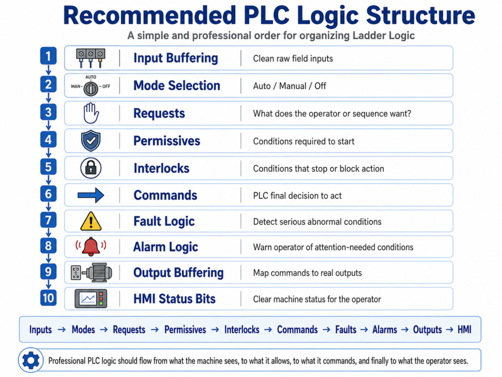
A Simple and Professional Way to Organize Ladder Logic
In industrial PLC programming, the logic should not be written randomly. A professional PLC program is usually organized in a clear sequence so technicians, engineers, and maintenance personnel can understand what the machine sees, what the operator wants, what is allowed, what is blocked, what is commanded, and what is finally energized.
A good structure makes the program easier to troubleshoot, safer to maintain, and more reliable in production.
A recommended ladder logic structure is:
- Input Buffering
- Mode Selection
- Requests
- Permissives
- Interlocks
- Commands
- Fault Logic
- Alarm Logic
- Output Buffering
- HMI Status Bits
1. Input Buffering
Purpose
Input buffering is where the PLC takes the raw physical inputs and converts them into clean internal bits used by the rest of the program.
Instead of using the physical input address everywhere in the logic, you create internal tags such as:
DI_Start_PB
DI_Stop_OK
DI_Motor_FB
DI_LS_Open
DI_LS_Closed
DI_PhotoEye_Clear
The raw input comes from the field device, but the internal buffered bit is what the program uses.
Why It Matters
Raw inputs can be noisy, inverted, or difficult to understand. Input buffering gives you one clean place to handle:
- Normally closed devices
- Field wiring logic
- Sensor debounce
- Signal conditioning
- Clear tag naming
- Troubleshooting from one location
Example
For a normally closed stop pushbutton or E-stop feedback:
Physical Input ON  = Stop circuit healthy
Physical Input OFF = Stop circuit open or faulted
Buffered logic:
XIC Local:1:I.Data.0 OTE DI_Stop_OKNow the rest of the program can simply use:
DI_Stop_OKThat is much easier to understand than using raw input addresses throughout the program.
2. Mode Selection
Purpose
Mode selection decides how the machine or device will operate.
Common modes include:
Manual Mode
Auto Mode
Maintenance Mode
Jog Mode
Bypass Mode
The mode logic should be handled early in the program because many other routines depend on the selected operating mode.
Example
For an HOA selector:
HAND = Manual control
OFF  = No operation
AUTO = Automatic control
Typical internal tags:
Mode_Manual
Mode_Auto
Mode_Off
Why It Matters
The machine should behave differently depending on the selected mode.
For example:
| Mode | Behavior |
|---|---|
| Manual | Operator directly requests movement |
| Auto | PLC sequence controls movement |
| Off | No command is allowed |
| Maintenance | Limited or special movement allowed |
Good mode logic prevents confusion and avoids mixing manual and automatic behavior in the same rung.
3. Requests
Purpose
A request is the operator’s or sequence’s intention.
A request does not directly energize an output. It only says:
“I want this action to happen.”
Examples:
Open_Request
Close_Request
Start_Request
Stop_Request
Fill_Request
Conveyor_Run_Request
Manual Request Example
Mode_Manual
Open_PB
Creates:
Open_RequestAuto Request Example
Mode_Auto
Auto_Close_Timer.DN
Creates:
Close_RequestWhy Requests Are Important
Requests separate intent from permission.
Just because the operator presses Open does not mean the motor should run. The PLC still needs to check permissives, interlocks, faults, and mode conditions.
This is one of the most important professional concepts in ladder logic.
4. Permissives
Purpose
A permissive is a condition that must be true before an action is allowed to start.
A permissive answers this question:
“Is it safe and acceptable to begin this action?”
Examples:
Stop_OK
No_Faults
Correct_Mode
Air_Pressure_OK
Guard_Closed
VFD_Ready
Door_Not_Already_Open
Example
For a door opening command, permissives may include:
DI_Stop_OK
No_Door_Faults
Mode_Auto OR Mode_Manual
Door_Not_Fully_Open
VFD_Ready
These conditions create:
Open_PermissiveImportant Concept
A permissive is normally checked before starting an action.
For example:
Open_Request
Open_Permissive
Then the PLC can create:
Open_Command5. Interlocks
Purpose
An interlock is a condition that can stop, block, or interrupt an action while it is happening.
An interlock answers this question:
“Should this action be stopped right now?”
Examples:
Stop_Pressed
E_Stop_Open
PhotoEye_Blocked
Opposite_Command_Active
Overload_Trip
Limit_Reached
Safety_Gate_Open
Difference Between Permissive and Interlock
This is very important.
| Concept | Main Function | Example |
|---|---|---|
| Permissive | Allows action to start | VFD Ready before starting motor |
| Interlock | Stops or prevents action during operation | Overload trips while motor is running |
Door Example
For a closing door:
Close_Commandmay be interrupted by:
PhotoEye_Blocked
Stop_Not_OK
Door_Fully_Closed
Open_Command_Active
These are interlocks because they can stop the closing movement.
6. Commands
Purpose
Commands are the PLC’s final decision that an action should happen.
A command is created when:
Request is active
Permissives are true
Interlocks are not active
Faults are not active
Correct mode is selected
Examples:
Motor_Start_Cmd
Open_Cmd
Close_Cmd
Conveyor_Run_Cmd
Pump_Start_Cmd
Valve_Open_Cmd
Example Command Logic
Open_Request
Open_Permissive
No_Open_Interlock
No_Faults
Creates:
Open_CmdImportant Rule
Commands should still be internal bits.
Do not energize the physical output directly from the command routine.
The command routine decides what should run.
The output buffering routine decides what physical output is energized.
That separation makes troubleshooting much cleaner.
7. Fault Logic
Purpose
Fault logic detects abnormal machine conditions that usually require operator or maintenance action.
A fault normally means:
“Something went wrong and the machine should stop or be prevented from operating.”
Faults are often latched until reset.
Common Fault Examples
Motor overload trip
Motor feedback missing
VFD fault
Sensor disagreement
Travel timeout
Door failed to open
Door failed to close
Emergency stop circuit lost
Example: Motor Feedback Fault
Command is ON, but feedback never turns ON.
Motor_Start_Cmd = ON
Motor_FB = OFF
Timer expires
Then latch:
Motor_Feedback_FaultWhy Faults Are Usually Latched
A fault should not disappear immediately just because the condition clears.
For example, if a motor overload trips and then cools down, the PLC should still tell the operator that a fault occurred.
A common structure is:
Fault condition detected  → Latch fault
Reset pushbutton + condition healthy → Unlatch fault
8. Alarm Logic
Purpose
Alarm logic warns the operator about abnormal or attention-required conditions.
An alarm does not always stop the machine.
An alarm means:
“Something needs attention, but the machine may still be able to operate.”
Common Alarm Examples
Low air pressure warning
Door left open too long
Tank level high warning
Filter needs service
Sensor unstable
Maintenance due
Communication warning
Fault vs Alarm
| Type | Stops Machine? | Requires Reset? | Example |
|---|---|---|---|
| Fault | Usually yes | Usually yes | Motor overload |
| Alarm | Not always | Sometimes acknowledge only | Low material warning |
Simple Rule
Use a fault when the condition affects safety, equipment protection, or machine operation.
Use an alarm when the condition is important for the operator to know but does not necessarily require stopping the equipment immediately.
9. Output Buffering
Purpose
Output buffering is the final routine where internal PLC commands are mapped to physical outputs.
This is where tags like:
Motor_Start_Cmd
Valve_Open_Cmd
Open_Cmd
Close_Cmd
energize real outputs such as:
Local:2:O.Data.0
Local:2:O.Data.1
Example
Open_Cmd    OTE Local:2:O.Data.0
Close_Cmd   OTE Local:2:O.Data.1
Or using internal output tags first:
Open_Cmd    OTE DO_Motor_Open
Close_Cmd   OTE DO_Motor_Close
Then:
DO_Motor_Open    OTE Local:2:O.Data.0
DO_Motor_Close   OTE Local:2:O.Data.1
Why Output Buffering Matters
Output buffering gives you one final place to verify:
- What is actually being energized
- Which command controls each output
- No duplicate output coils
- Safe output mapping
- Easier troubleshooting
A professional program should avoid energizing the same physical output in multiple routines.
10. HMI Status Bits
Purpose
HMI status bits are internal tags created specifically to display clear machine conditions to the operator.
The HMI should not need to interpret complicated ladder logic. The PLC should provide clean status bits.
Examples
Door_Open_Status
Door_Closed_Status
Door_Moving_Status
Door_Ajar_Status
Motor_Running_Status
Fault_Active_Status
Alarm_Active_Status
Auto_Mode_Status
Manual_Mode_Status
Ready_To_Run_Status
Why HMI Status Bits Are Important
Good HMI status bits help operators and maintenance understand the machine quickly.
Instead of showing raw inputs only, the HMI should show meaningful machine states:
| Poor HMI Display | Better HMI Display |
|---|---|
| LS1 = ON | Door Fully Open |
| I:1/3 = OFF | Stop Circuit Not Healthy |
| B3:2/5 = ON | Motor Feedback Fault |
| T4:0/DN = ON | Auto Close Timer Done |
The PLC should translate field signals into clear operational status.
Recommended Order in Ladder Logic
A professional PLC scan structure should usually follow this order:
1. Input Buffering
2. Mode Selection
3. Requests
4. Permissives
5. Interlocks
6. Commands
7. Fault Logic
8. Alarm Logic
9. Output Buffering
10. HMI Status Bits
This order works because the logic flows naturally:
Read inputs
Determine mode
Capture operator or sequence requests
Check if action is allowed
Check if action must be blocked
Generate commands
Detect faults
Detect alarms
Energize outputs
Display status to HMI
Simple Industrial Flow
A clean way to understand the structure is:
INPUTS
  ↓
MODES
  ↓
REQUESTS
  ↓
PERMISSIVES
  ↓
INTERLOCKS
  ↓
COMMANDS
  ↓
FAULTS / ALARMS
  ↓
OUTPUTS
  ↓
HMI STATUS
Another simple version:
What do I see?
What mode am I in?
What does the operator or sequence want?
Am I allowed to do it?
Is anything blocking it?
Should I command it?
Did something go wrong?
What output should turn on?
What should the operator see?
Example: Industrial Door Logic
For an industrial door, the structure may look like this:
Input Buffering
DI_Open_PB
DI_Close_PB
DI_Stop_OK
DI_LS_Open
DI_LS_Closed
DI_PhotoEye_Clear
DI_Motor_FB
DI_Overload_OK
Mode Selection
Mode_Manual
Mode_Auto
Requests
Open_Request
Close_Request
Auto_Close_Request
Permissives
Open_Permissive
Close_Permissive
Example:
Close_Permissive =
Stop_OK
No_Faults
Door_Not_Fully_Closed
Mode_Auto OR Mode_Manual
Interlocks
Close_Interlock =
PhotoEye_Blocked
Stop_Not_OK
Open_Command_Active
Door_Fully_Closed
Overload_Trip
Commands
Close_Cmd =
Close_Request
Close_Permissive
No_Close_Interlock
Fault Logic
Close_Timeout_Fault
Motor_Feedback_Fault
Overload_Fault
Limit_Switch_Disagreement_Fault
Alarm Logic
Door_Ajar_Alarm
Door_Open_Too_Long_Alarm
PhotoEye_Blocked_Alarm
Output Buffering
Close_Cmd → Motor_Close_Output
Open_Cmd  → Motor_Open_Output
HMI Status Bits
Door_Open_Status
Door_Closed_Status
Door_Ajar_Status
Door_Closing_Status
Door_Opening_Status
Fault_Active
Alarm_Active
Ready_To_Run
Important Best Practices
1. Do Not Use Raw Inputs Everywhere
Avoid this:
Local:1:I.Data.0all over the program.
Use this instead:
DI_Stop_OKThis makes the program easier to read and troubleshoot.
2. Do Not Mix Requests and Outputs
Avoid making the pushbutton directly energize the motor output.
Poor structure:
Open_PB → Motor_Open_OutputBetter structure:
Open_PB → Open_Request
Open_Request + Open_Permissive + No_Interlock → Open_Cmd
Open_Cmd → Motor_Open_Output
3. Keep Faults Separate from Alarms
Do not treat every abnormal condition the same.
A fault usually stops or prevents operation.
An alarm usually warns the operator.
4. Avoid Duplicate Output Coils
The same physical output should not be controlled in multiple places.
Bad practice:
Routine 1 → OTE Motor_Output
Routine 5 → OTE Motor_Output
Routine 9 → OTE Motor_Output
Better practice:
Command Logic → Motor_Cmd
Output Buffer → Motor_Output
5. Make HMI Bits Easy to Understand
The HMI should show operator-friendly information, not raw PLC logic.
Use names like:
Door Ready
Door Opening
Door Closing
Door Ajar
Fault Active
Reset Required
not just internal addresses.
Final Thoughts
A professional PLC program should be organized so the logic tells a clear story.
The PLC should first read and clean the inputs, determine the operating mode, process requests, check permissives and interlocks, generate commands, detect faults and alarms, energize outputs, and finally send clear status information to the HMI.
This structure makes ladder logic easier to understand, easier to troubleshoot, and safer to maintain in a real industrial environment.
A simple way to remember it is:
Inputs → Modes → Requests → Permissives → Interlocks → Commands → Faults → Alarms → Outputs → HMIThis approach is especially useful for motors, conveyors, doors, pumps, valves, VFDs, and other industrial devices where reliable control and clear troubleshooting are critical.