11. Industrial Sensors: The Eyes and Ears of the PLC (11 of 41)
In industrial automation, the PLC does not know what is happening in the real world unless field devices send information back to it.
That is the job of sensors.
Sensors detect physical conditions such as:
Object present
Object missing
Position reached
Door closed
Cylinder extended
Tank level high
Pressure low
Temperature high
Motor running
Conveyor moving
Label detected
Box jammed
A PLC can execute logic, control outputs, run timers, and make decisions, but it depends on sensors to know the actual machine condition.
A simple way to say it:
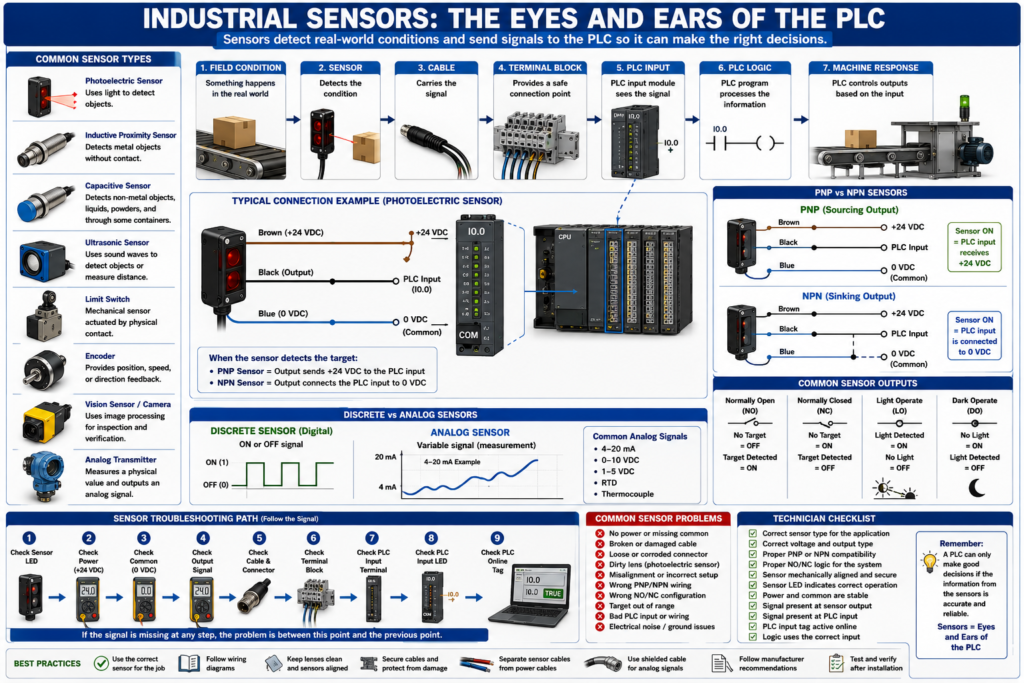
Sensors are the eyes and ears of the PLC.
Without reliable sensor feedback, the PLC is blind.
1. What Is an Industrial Sensor?
An industrial sensor is a device that detects a physical condition and sends a signal to the control system.
The signal may go to:
PLC input module
Remote I/O module
Safety controller
VFD input
HMI through controller
SCADA system
Basic sensor flow:
Physical condition
      ↓
Sensor detects condition
      ↓
Sensor output changes
      ↓
PLC input turns ON or changes value
      ↓
PLC logic reacts
Example:
Box arrives at photoeye
      ↓
Photoeye output turns ON
      ↓
PLC input turns ON
      ↓
PLC stops conveyor or starts next sequence
2. Discrete Sensors vs Analog Sensors
Industrial sensors can be divided into two major categories:
Discrete sensors
Analog sensors
Discrete Sensors
A discrete sensor is ON or OFF.
It gives a digital signal.
Examples:
Photoeye detects product: ON/OFF
Proximity sensor detects metal: ON/OFF
Limit switch actuated: ON/OFF
Pressure switch made: ON/OFF
Level switch active: ON/OFF
PLC example:
Sensor ON  = PLC input TRUE
Sensor OFF = PLC input FALSE
Discrete sensors are commonly wired to digital input modules.
Analog Sensors
An analog sensor gives a variable signal.
It represents a measurement.
Examples:
Pressure transmitter
Temperature transmitter
Level transmitter
Flow transmitter
Load cell system
Position transmitter
Common analog signals:
4–20 mA
0–10 VDC
1–5 VDC
RTD
Thermocouple
PLC example:
4 mA  = 0 PSI
20 mA = 100 PSI
Analog sensors are commonly wired to analog input modules.
3. Why Sensors Matter
Sensors are critical because they tell the PLC the real status of the machine.
A machine sequence may depend on sensors for:
Starting
Stopping
Indexing
Counting
Positioning
Filling
Rejecting
Sorting
Safety monitoring
Fault detection
Quality checks
Examples:
A conveyor starts only when a downstream sensor is clear.
A filler stops when the bottle is detected in position.
A labeler rejects a product if the label is missing.
A door stops opening when the open limit switch is reached.
A pump stops when tank level is low.
If a sensor fails, the machine may stop, fault, miscount, overfill, underfill, or operate unsafely.
4. Common Industrial Sensors
Photoelectric Sensors
Photoelectric sensors use light to detect objects.
They are commonly used for:
Box detection
Bottle detection
Product counting
Label detection
Conveyor tracking
Jam detection
Presence detection
Common types:
Through-beam
Retroreflective
Diffuse
Background suppression
Color/contrast sensors
Photoeyes are very common on packaging lines and conveyors.
Inductive Proximity Sensors
Inductive proximity sensors detect metal.
They are commonly used for:
Cylinder position
Machine position
Metal part detection
Rotating target detection
Valve actuator feedback
Conveyor position
They do not require physical contact.
They detect metal objects when the target enters the sensing field.
Capacitive Sensors
Capacitive sensors can detect non-metal materials.
They may detect:
Plastic
Glass
Liquids
Powders
Granules
Cardboard
Wood
Some solids through containers
They are useful when the target is not metal.
Ultrasonic Sensors
Ultrasonic sensors use sound waves to measure distance or detect objects.
They are commonly used for:
Level detection
Distance measurement
Object presence
Web loop control
Tank level
Irregular surface detection
They are useful when color, transparency, or surface finish causes problems for optical sensors.
Limit Switches
Limit switches are mechanical sensors.
They detect physical position when something contacts the actuator.
Common uses:
Door open/closed
Guard position
Cylinder end of travel
Machine home position
Mechanical travel limit
Limit switches are simple and reliable, but they have moving parts that can wear out.
Encoders
Encoders provide position or speed feedback.
Common uses:
Conveyor speed
Motor shaft position
Servo position
Length measurement
Indexing systems
Cut-to-length systems
Position tracking
Common encoder types:
Incremental encoder
Absolute encoder
Encoders are more advanced than simple ON/OFF sensors because they provide motion or position information.
Vision Sensors and Cameras
Vision sensors use image processing to inspect products.
They may detect:
Label present
Barcode readable
Correct cap
Correct orientation
Date code present
Product defect
Color match
Position verification
A vision sensor may send a pass/fail signal to the PLC or communicate detailed inspection data over Ethernet.
5. Field Devices vs Sensors
All sensors are field devices, but not all field devices are sensors.
Field devices include anything mounted outside the PLC cabinet that interacts with the machine or process.
Examples:
Sensors
Push buttons
Stack lights
Solenoid valves
Motors
VFDs
Valves
Transmitters
Actuators
Encoders
Cameras
Remote I/O
Safety switches
Sensors usually send information to the PLC.
Outputs and actuators usually receive commands from the PLC.
Simple difference:
Sensor = tells the PLC what is happening
Actuator = does physical work based on PLC command
6. Sensor Wiring Basics
Many DC sensors use 3 wires.
Common color code:
Brown = +24 VDC
Blue  = 0 VDC / Common
Black = Signal output
Basic 3-wire sensor:
+24 VDC → Brown
0 VDC  → Blue
Signal → Black to PLC input
When the sensor detects the target, the output changes state and the PLC input should turn ON or OFF depending on the wiring and sensor type.
7. PNP and NPN Sensors
This is one of the most important sensor wiring concepts.
PNP Sensor
A PNP sensor switches positive voltage to the PLC input.
PNP = sensor output sends +24 VDC to the inputOften called:
Sourcing outputBasic idea:
Sensor ON → PLC input receives +24 VDCNPN Sensor
An NPN sensor switches the PLC input to 0 VDC/common.
NPN = sensor output switches to commonOften called:
Sinking outputBasic idea:
Sensor ON → PLC input is connected to 0 VDCImportant:
The sensor type must match the PLC input wiring design.
A PNP sensor wired to the wrong input type may not work correctly.
8. Normally Open and Normally Closed Sensor Outputs
Sensors may be configured as:
Normally Open
Normally Closed
Light Operate
Dark Operate
Complementary outputs
Normally Open
The output is OFF when the target is not detected.
No target = OFF
Target detected = ON
Normally Closed
The output is ON when the target is not detected.
No target = ON
Target detected = OFF
The best choice depends on the machine design and fault detection needs.
For example, some systems prefer a normally closed signal so a broken wire can be detected as a missing healthy signal.
9. Sensor Alignment and Adjustment
Many sensors require proper setup.
Photoelectric sensors may need:
Correct alignment
Correct reflector position
Correct sensitivity
Clean lens
Correct teach setting
Correct light/dark mode
Proper mounting angle
Proximity sensors may need:
Correct sensing distance
Correct metal target
Proper mounting
No mechanical damage
No loose bracket
Ultrasonic sensors may need:
Correct range
Stable target surface
Proper angle
No strong air turbulence
No blocked sensing path
A sensor can be electrically good but mechanically misaligned.
10. Sensor Feedback in PLC Logic
Sensor signals are often used as feedback.
Examples:
Cylinder extend command ON, but extended sensor does not turn ON.
Door opening command ON, but open limit switch does not turn ON.
Conveyor running command ON, but encoder pulses are missing.
Bottle expected, but photoeye does not detect bottle.
Good PLC logic compares command vs feedback.
Example:
Cylinder extend command ON
AND extended sensor OFF after 2 seconds
= Cylinder extend fault
This helps the machine detect real-world failure.
11. Common Sensor Problems
Common sensor issues include:
No power
Missing common
Broken cable
Loose connector
Dirty lens
Misalignment
Wrong sensor type
Wrong PNP/NPN wiring
Incorrect teach setting
Target too far away
Reflector missing
Mechanical damage
Water ingress
Bad PLC input
Incorrect PLC address/tag
Electrical noise
Many sensor problems are simple, but they must be checked logically.
12. Sensor Troubleshooting Method
When a PLC does not see a sensor input, follow the signal.
Do not guess.
Use this method:
1. Check the sensor LED.
2. Check sensor power.
3. Check the common/0 VDC.
4. Check the output signal wire.
5. Check the cable and connector.
6. Check terminal block signal.
7. Check PLC input terminal.
8. Check PLC input LED.
9. Check online PLC tag.
10. Check logic using the sensor.
For a 3-wire sensor:
Brown to Blue = 24 VDC
Black to Blue = signal output
If the sensor LED changes but the PLC input does not, the problem may be:
Broken signal wire
Bad terminal
Wrong input wiring
Bad PLC input card
Missing common
Wrong PNP/NPN type
13. Sensor Troubleshooting Example
Problem
A box is present, but the conveyor does not stop.
The HMI shows:
Box Present Sensor OFFStep 1 — Check sensor LED
If the LED does not change, check:
Sensor alignment
Target position
Dirty lens
Sensor power
Teach setting
Sensor damage
Step 2 — Check power
Measure:
Brown to Blue = approximately 24 VDCIf no voltage is present, check:
Fuse
Power supply
Terminal block
Cable
Connector
0 VDC common
Step 3 — Check output
Measure:
Black to Blue = output signalIf output changes at the sensor but not at the PLC, check:
Cable
Terminal block
PLC input wiring
Input module common
PLC input LED
Step 4 — Check PLC
If the input LED is ON but the program does not respond, check:
Correct input tag
Input buffering
Forces
Routine being scanned
XIC/XIO usage
Faulted module
14. Sensor Selection Basics
When selecting or replacing a sensor, verify:
Voltage
Output type
PNP or NPN
Normally open or normally closed
Connector type
Sensing distance
Target material
Mounting style
Environmental rating
Cable length
Response time
Analog or discrete output
Communication type
Never replace a sensor only by physical appearance.
Two sensors may look the same but have different outputs or wiring.
15. Sensors and Safety
Not all sensors are safety-rated.
A standard photoeye or proximity sensor should not be used as a safety device unless it is specifically designed and rated for safety.
Safety devices may include:
Safety light curtain
Safety interlock switch
Safety scanner
Safety mat
Safety-rated magnetic switch
Safety-rated RFID switch
These devices are designed to work with safety relays or safety PLCs.
Important:
Standard sensor = machine control
Safety-rated sensor = personnel protection
Do not confuse the two.
16. Common Mistakes New Technicians Make
Mistake 1 — Blaming the PLC before checking the sensor
Always check the field device first.
Mistake 2 — Checking only +24 VDC
The sensor also needs 0 VDC/common.
Mistake 3 — Ignoring PNP/NPN compatibility
Wrong output type can prevent the PLC input from turning ON.
Mistake 4 — Ignoring mechanical alignment
A sensor may be electrically healthy but physically misaligned.
Mistake 5 — Replacing a sensor without checking the cable
A damaged cable or connector can look like a bad sensor.
Mistake 6 — Not checking the PLC online tag
The input LED may be ON, but the program may use a different tag or buffered bit.
17. Technician Checklist
When troubleshooting a sensor, verify:
Sensor type
Sensor voltage
PNP/NPN output
NO/NC output
Connector and cable condition
Sensor LED operation
Target alignment
Sensor power
0 VDC/common
Output signal
Terminal block signal
PLC input LED
PLC input tag online
Input buffering logic
Correct routine being scanned
No active forces
Environmental issues
Final Thoughts
Sensors are one of the most important parts of any automation system.
They tell the PLC what is happening in the real world.
A PLC can only make good decisions if the information coming from the field is accurate and reliable.
When troubleshooting, remember:
Sensor → Cable → Terminal Block → PLC Input → PLC LogicFollow the signal step by step.
Do not guess.
Do not replace parts blindly.
Check power.
Check common.
Check output.
Check the PLC input.
Check the logic.
The PLC controls the machine, but sensors tell the PLC what the machine is actually doing.
Understanding sensors is one of the biggest steps toward becoming a confident automation technician.