2. Basic Electricity for Automation Technicians
Electricity is the foundation of industrial automation.
Before a technician can troubleshoot PLCs, sensors, VFDs, relays, motors, HMIs, or control panels, they must understand the basic electrical concepts that make everything work.
Many automation problems are not programming problems.
They are electrical problems.
A PLC input may not turn on because a sensor has no power.
A motor may not start because an overload is tripped.
A relay may not energize because the common wire is missing.
A VFD may fault because of a power issue.
A 24 VDC power supply may drop voltage because too many devices are connected.
That is why every automation technician needs to understand:
Voltage
Current
Resistance
Power
AC
DC
Control voltage
Power circuits
Grounding
Electrical measurements
The goal is not only to know the theory.
The goal is to use the theory to troubleshoot real machines.
1. What Is Voltage?
Voltage is electrical pressure.
It is the force that pushes electrons through a circuit.
A simple way to think about it:
Voltage = Electrical pressureIn industrial automation, common voltages include:
| Voltage | Common Use |
|---|---|
| 24 VDC | PLC inputs, sensors, relays, solenoids |
| 120 VAC | Control circuits, coils, older control panels |
| 240 VAC | Small motors, heaters, single-phase equipment |
| 480 VAC | Industrial motors, VFDs, large equipment |
Voltage by itself does not mean a device is working. You can have voltage present, but the circuit may still fail if there is no complete path for current to flow.
Technician example
A sensor has 24 VDC on the brown wire, but the sensor does not turn on.
Possible causes:
Missing 0V/common
Broken wire
Bad sensor
Incorrect wiring
Short circuit
Bad power supply
So when troubleshooting, do not only ask:
Do I have voltage?Also ask:
Do I have a complete circuit?2. What Is Current?
Current is the movement of electrical charge through a circuit.
A simple way to think about it:
Current = Electrical flowCurrent is measured in amps.
In automation, current matters because devices require a certain amount of current to operate.
Examples:
A sensor may require a few milliamps.
A relay coil may require more current.
A solenoid valve may require even more.
A motor may require several amps.
If a power supply cannot provide enough current, the voltage may drop and devices may behave incorrectly.
Technician example
A 24 VDC power supply measures 24 VDC with no load, but when the machine starts, the voltage drops to 18 VDC.
Possible causes:
Power supply overloaded
Short circuit
Bad device pulling too much current
Loose connection
Undersized power supply
This is why checking voltage under load is important.
3. What Is Resistance?
Resistance opposes current flow.
A simple way to think about it:
Resistance = Opposition to currentResistance is measured in ohms.
Some resistance is normal. For example:
Relay coils have resistance.
Solenoid coils have resistance.
Motor windings have resistance.
Heating elements have resistance.
But too much resistance can create a problem.
Bad connections, corroded terminals, damaged wires, and loose screws can increase resistance.
Technician example
A solenoid valve receives voltage, but it does not energize correctly.
Possible causes:
Bad coil
Loose terminal
High-resistance connection
Voltage drop
Weak power supply
Mechanical valve issue
A high-resistance connection can cause voltage to appear normal with a meter but fail when the device tries to operate.
4. What Is Power?
Power is the rate at which electrical energy is used.
Power is measured in watts.
Basic formula:
Power = Voltage × CurrentOr:
Watts = Volts × AmpsExamples:
24 VDC × 1 A = 24 W
120 VAC × 2 A = 240 W
480 VAC × 10 A = 4800 W
In control panels, power matters when sizing:
Power supplies
Transformers
Fuses
Breakers
Wires
Contactors
Relays
VFDs
A device must be powered correctly and protected correctly.
5. Ohm’s Law
Ohm’s Law connects voltage, current, and resistance.
Voltage = Current × ResistanceOr:
V = I × RWhere:
| Symbol | Meaning |
|---|---|
| V | Voltage |
| I | Current |
| R | Resistance |
You do not need to be a mathematician to be a good automation technician, but you should understand the relationship.
If voltage increases and resistance stays the same, current increases.
If resistance increases and voltage stays the same, current decreases.
Practical meaning
A loose or corroded connection adds resistance.
That extra resistance can reduce current flow and create voltage drop.
This can cause:
Weak relay operation
Solenoid not shifting
Sensor instability
PLC input flickering
VFD control issues
Overheating terminals
Intermittent machine faults
6. AC vs DC
Automation technicians must understand the difference between AC and DC.
DC — Direct Current
DC flows in one direction.
Common DC voltage in automation:
24 VDCUsed for:
PLC inputs
PLC outputs
Sensors
Photo eyes
Proximity switches
Relays
Solenoid valves
Analog transmitters
Control circuits
24 VDC is very common because it is safer, reliable, and works well with PLC systems.
AC — Alternating Current
AC changes direction many times per second.
Common AC voltages in industry:
120 VAC
240 VAC
480 VAC
Used for:
Motors
Heaters
Transformers
Power supplies
VFD input power
Older control circuits
Lighting
In many plants, 480 VAC powers the motor or VFD, while 24 VDC controls the logic.
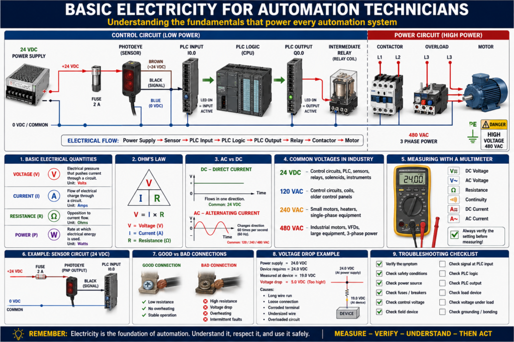
7. Control Circuit vs Power Circuit
One of the most important concepts in industrial automation is the difference between control power and power circuits.
Control circuit
The control circuit uses lower power signals to make decisions or energize control devices.
Examples:
24 VDC sensor circuit
PLC input circuit
PLC output circuit
Relay coil circuit
Contactor coil circuit
Solenoid valve circuit
Power circuit
The power circuit carries the energy that drives the load.
Examples:
Motor power
Heater power
VFD output to motor
Pump power
Conveyor motor power
A PLC usually controls the machine indirectly.
Example:
PLC Output
   ↓
Relay Coil
   ↓
Contactor Coil
   ↓
Motor Power Contacts
   ↓
Motor Runs
The PLC does not directly power the motor. It controls the device that controls the motor power.
8. 24 VDC in Automation
24 VDC is one of the most important voltages for automation technicians.
It is commonly used for:
Sensors
PLC inputs
PLC outputs
Relays
Solenoid valves
Light towers
Analog instruments
HMI control circuits
Remote I/O
A basic 24 VDC circuit includes:
+24 VDC
Device
Signal or load
0 VDC/common
For the circuit to work, both the positive side and the common side must be correct.
Common mistake
A technician checks only the positive side and sees 24 VDC, but the device still does not work.
Why?
Because the common may be missing.
Always verify the complete circuit:
+24 VDC path
Device
Signal/output path
0 VDC common return
9. Voltage Drop
Voltage drop happens when voltage is lost across a wire, connection, contact, or device.
Some voltage drop is normal, but too much causes problems.
Common causes:
Long wire runs
Loose terminals
Corroded contacts
Undersized wire
Overloaded circuit
Bad relay contact
Bad fuse holder
Damaged cable
Technician example
A solenoid valve is rated for 24 VDC, but only receives 19 VDC when energized.
Possible result:
Valve does not shift
Valve chatters
Machine faults
Intermittent operation
This is why measuring voltage while the device is energized is important.
10. Fuses and Breakers
Fuses and breakers protect circuits from excessive current.
They do not exist to protect the PLC program.
They exist to protect:
Wiring
Devices
Power supplies
Transformers
Panels
People
Equipment
Fuse
A fuse opens the circuit when too much current flows.
Once blown, it must be replaced.
Breaker
A breaker trips when too much current flows.
It can usually be reset after the fault is corrected.
Important:
Never replace a blown fuse without asking why it blew.
A blown fuse is usually a symptom, not the root cause.
Possible causes:
Short circuit
Ground fault
Failed device
Wrong fuse size
Damaged wire
Overloaded circuit
Incorrect wiring
11. Grounding and Bonding
Grounding and bonding are important for safety and noise reduction.
Grounding
Grounding provides a reference to earth and helps safely clear faults.
Bonding
Bonding connects metal parts together so they are at the same electrical potential.
Examples:
Panel door bonded to enclosure
Motor frame bonded to ground
Control panel bonded to machine frame
Cable shields grounded properly
Ground bar connected to protective earth
Good grounding and bonding help with:
Electrical safety
Fault clearing
Noise reduction
VFD noise control
Stable analog signals
Reliable communication
Poor grounding can create strange problems:
Noisy analog signals
Communication faults
Sensor flickering
VFD interference
Intermittent PLC inputs
Unstable machine behavior
12. Using a Multimeter
The multimeter is one of the most important tools for an automation technician.
You should be comfortable measuring:
AC voltage
DC voltage
Resistance
Continuity
Current
Diode check
Common meter checks
| Check | Purpose |
|---|---|
| 24 VDC power | Verify control voltage |
| 120 VAC | Verify control transformer or AC control |
| 480 VAC | Verify motor/VFD supply power |
| Continuity | Check wire, fuse, or contact path |
| Resistance | Check coils, windings, and circuits |
| Voltage drop | Find bad connections under load |
Important safety note
Always confirm your meter is set correctly before measuring voltage.
Using the wrong setting or wrong input jack can damage the meter or create a safety hazard.
13. Basic Troubleshooting Method
When troubleshooting electrical problems, follow a method.
Do not jump randomly from device to device.
A simple method:
1. Verify the symptom.
2. Check safety conditions.
3. Check power source.
4. Check fuses and breakers.
5. Check control voltage.
6. Check the field device.
7. Check the signal at the PLC input.
8. Check the PLC logic.
9. Check the PLC output.
10. Check the load device.
For PLC-related problems, think:
Input → Logic → OutputFor electrical circuits, think:
Source → Protection → Control Device → Load → Return PathThis method helps you find where the circuit stops working.
14. Real-World Example: Sensor Not Turning On PLC Input
Problem:
A photoeye detects a box, but the PLC input does not turn on.Step-by-step checks:
Step 1 — Check sensor power
Measure between brown and blue wires:
Brown = +24 VDC
Blue = 0 VDC
Expected:
Approximately 24 VDCStep 2 — Check sensor operation
Look at the sensor LED.
Does it change when the box is present?
Yes → Sensor detects object.
No → Sensor may be misaligned, dirty, failed, or not powered.
Step 3 — Check output signal
Measure the sensor output wire.
Common color:
Black = Signal outputExpected:
Signal changes when sensor changes state.Step 4 — Check PLC input LED
If signal reaches the PLC input, the input LED should turn on.
If not:
Broken wire
Wrong terminal
Bad common
Bad input card
Wrong sensor type
Incorrect PNP/NPN wiring
Step 5 — Check PLC program online
If the PLC input LED is ON but the logic does not respond, check:
Input address/tag
Input buffering logic
Forces
Faulted module
Wrong rung condition
Incorrect XIC/XIO instruction
This is how electrical troubleshooting connects to PLC troubleshooting.
15. Real-World Example: Motor Does Not Start
Problem:
Operator presses Start, but motor does not run.Do not immediately blame the PLC.
Check the system step by step:
Is the E-stop healthy?
Is the overload reset?
Is the VFD faulted?
Is the PLC seeing the Start command?
Is the PLC output turning on?
Is the relay energizing?
Is the contactor pulling in?
Is motor power present?
Is the motor mechanically jammed?
A professional technician proves each step.
Common Mistakes New Technicians Make
Mistake 1 — Checking only voltage, not the full circuit
You may see voltage but still have no complete return path.
Mistake 2 — Blaming the PLC too quickly
Many PLC problems are actually field wiring, sensor, relay, fuse, or power supply problems.
Mistake 3 — Replacing parts without testing
Replacing parts without proof can waste time and money.
Mistake 4 — Ignoring the common wire
Many 24 VDC problems are caused by missing or incorrect 0V/common connections.
Mistake 5 — Not checking voltage under load
A circuit may look good with no load but fail when the device turns on.
Mistake 6 — Not using drawings
Electrical drawings help you follow the circuit logically.
Technician Checklist
Before blaming the PLC program, verify:
Control voltage is present.
Power supply is healthy.
Fuses are good.
Breakers are not tripped.
Common/0V is connected.
Sensor has power.
PLC input LED changes.
PLC output LED changes.
Relay or contactor energizes.
Load receives voltage.
Grounding and bonding are correct.
No loose terminals are present.
Final Thoughts
Basic electricity is not just theory.
It is the foundation of real industrial troubleshooting.
Every PLC input, output, sensor, relay, solenoid, motor starter, VFD, HMI, and control panel depends on electrical principles.
If you understand voltage, current, resistance, power, AC, DC, control circuits, power circuits, fuses, grounding, and voltage drop, you will troubleshoot faster and with more confidence.
The best automation technicians do not guess.
They follow the circuit.
They verify voltage.
They prove the signal.
They check the load.
They understand the system.
Before blaming the PLC, prove the electrical path.
That mindset is what separates a parts changer from a professional automation technician.