9. PLC Troubleshooting: Inputs, Logic, Outputs, and Field Devices
How to Diagnose PLC-Controlled Circuits Without Guessing
PLC troubleshooting is one of the most important skills for an automation or maintenance technician. In modern industrial panels, the PLC is often the center of the control system. It reads field devices, processes logic, and commands outputs.
But when a machine does not work correctly, the PLC is not always the problem.
The real issue may be:
A failed sensor
A broken field wire
A missing 24 VDC supply
An open common
A bad input signal
A logic condition not satisfied
A missing output common
A blown output fuse
A failed solenoid coil
A mechanical issue in the field
A good technician does not immediately blame the PLC.
A good technician follows the signal path.
Many PLC-related problems are connected to the input/output devices associated with the system, and that PLC troubleshooting allows the technician to monitor the control program in real time while still using a systematic troubleshooting method.
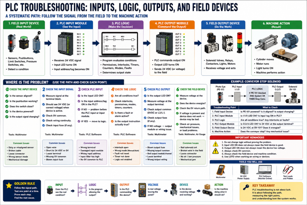
1. The PLC Troubleshooting Path
A PLC-controlled system can be understood as a chain:
Field Input Device
        ↓
PLC Input Module
        ↓
PLC Logic
        ↓
PLC Output Module
        ↓
Field Output Device
        ↓
Machine Action
For example:
Photo Eye detects box
        ↓
PLC input turns ON
        ↓
PLC logic allows conveyor stop
        ↓
PLC output energizes relay or solenoid
        ↓
Field device actuates
        ↓
Machine responds
If the machine does not respond, the technician must determine where this chain breaks.
2. Do Not Start by Editing Logic
One of the worst habits in PLC troubleshooting is changing logic before proving the field condition.
If the machine was running yesterday and no program change was made, the problem is often outside the PLC program.
Possible causes include:
Sensor misalignment
Damaged cable
Loose terminal
Blown fuse
Bad relay
Missing output power
Open safety circuit
Failed solenoid coil
Mechanical jam
No air pressure
No motor power
Before changing the program, ask:
Is the PLC receiving the correct input?
Is the logic condition true?
Is the PLC commanding the output?
Is voltage leaving the output module?
Is the field device receiving voltage?
Is the device mechanically able to operate?
PLC troubleshooting should be evidence-based, not guess-based.
3. Start with the Symptom
Before going online with the PLC, define the problem clearly.
Ask:
What device is not working?
What should happen?
What is actually happening?
Is the issue automatic only?
Does manual mode work?
Does the HMI show an alarm?
Are inputs changing?
Are outputs energizing?
Is the fault electrical, logical, or mechanical?
Example symptoms:
| Symptom | Possible Direction |
|---|---|
| Sensor does not show in PLC | Check field device, wiring, input module, common |
| PLC input is ON but logic does not run | Check permissives, interlocks, mode, sequence state |
| PLC output LED is ON but device is OFF | Check output power, fuse, wiring, field device |
| PLC output does not turn ON | Check logic conditions and output instruction |
| Device energizes but machine does not move | Check pneumatic, hydraulic, mechanical, motor load |
| Output turns ON/OFF rapidly | Check logic chatter, unstable input, debounce, interlock |
The first step is always to understand the symptom before testing.
4. PLC Inputs: Does the PLC See the Field Device?
A PLC input represents a real-world condition.
Examples:
Start pushbutton pressed
Stop pushbutton healthy
Photo eye blocked
Limit switch made
Pressure switch satisfied
Overload contact healthy
Motor feedback running
Tank level high
Door closed
The troubleshooting question is:
Is the field condition reaching the PLC input?
Input troubleshooting path
Sensor / Pushbutton / Switch
        ↓
Field cable
        ↓
Terminal block
        ↓
PLC input terminal
        ↓
PLC input LED
        ↓
PLC input tag / address
If the input is not changing in the PLC, check each point in the path.
5. Example: Photo Eye Does Not Turn ON PLC Input
Symptom:
A box is present, but the PLC input does not turn ON.
Possible causes:
Photo eye not powered
Photo eye misaligned
Wrong light/dark mode
Dirty lens
Broken cable
Loose connector
Bad terminal
Missing 0V common
Wrong input terminal
Bad PLC input channel
Step-by-step:
Step 1 — Check sensor power
Measure +24 VDC to 0VDC at the sensor.
Expected: approximately 24 VDC
If power is missing, troubleshoot sensor supply and wiring.
Step 2 — Check sensor output
Measure the sensor output wire to 0VDC while actuating the sensor.
Expected: output changes state
If the sensor output does not change, the sensor may be misaligned, failed, dirty, or configured incorrectly.
Step 3 — Check signal at terminal block
Measure the input signal at the panel terminal.
If the signal exists at the sensor but not at the panel, suspect field wiring or connector.
Step 4 — Check PLC input terminal and LED
Verify voltage reaches the PLC input terminal.
Check the input LED.
Check the input tag online.
If voltage reaches the input terminal but the PLC input does not turn ON, check the input common, wiring type, module status, or input channel.
6. PLC Logic: Is the Condition Actually True?
Once the PLC sees the input, the next question is:
Is the logic allowing the output to energize?
A PLC output usually depends on several conditions.
Example:
Motor_Run_Command =
Start_Request
AND Stop_OK
AND Safety_OK
AND Auto_Mode
AND No_Fault
AND Overload_OK
AND Downstream_Clear
In ladder logic, that may look like:
Start Request → Stop OK → Safety OK → No Fault → Motor Output
If one condition is false, the output will not energize.
This is where online monitoring is helpful. The manual explains that PLC troubleshooting differs from basic circuits because the technician can monitor the control program in real time, although the logic is monitor-only in the training environment.
7. Common PLC Logic Conditions That Block Outputs
When the PLC input is good but the output does not turn ON, check for logic conditions.
Common blockers:
Machine not in Auto
Start request not latched
E-stop not healthy
Safety relay not reset
Overload fault active
Permissive missing
Interlock active
Sequence not in correct state
Timer not done
Alarm not acknowledged
HMI command not active
Mode mismatch
Manual/Auto conflict
Fault latch not reset
Example:
The start pushbutton works.
The motor output does not turn ON.
Possible reason:
The motor overload fault bit is latched.
Or:
The machine is not in Auto mode.
Or:
A downstream conveyor permissive is missing.
A good technician checks the logic conditions before blaming the output module.
8. PLC Outputs: Is the PLC Commanding the Device?
Once logic is true, the PLC should command an output.
Output examples:
Motor starter coil
Interposing relay
Solenoid valve
Pilot light
Alarm horn
Stack light
VFD run command
Valve open command
Conveyor start command
The troubleshooting question is:
Is the PLC output command ON?
Check:
Output instruction in logic
Output tag/address
Output LED on module
Voltage at output terminal
Output common or source power
Output fuse
Terminal block
Field device voltage
Important:
PLC output LED ON does not always mean the field device has voltage.
The LED usually means the output is being commanded internally. It does not always prove that voltage is reaching the physical device.
9. PLC Output LED ON but Field Device OFF
This is one of the most common PLC panel troubleshooting scenarios.
Symptom:
PLC output LED is ON.
Solenoid valve does not energize.
Possible causes:
No output common
Blown output fuse
Bad output module channel
Loose terminal
Broken field wire
Bad solenoid coil
Missing 0V common
Bad connector
Wrong terminal
No air pressure
Mechanical valve stuck
Troubleshooting path:
PLC Output Command
        ↓
Output LED
        ↓
Output Terminal Voltage
        ↓
Terminal Block
        ↓
Field Cable
        ↓
Solenoid Coil
        ↓
0V Common Return
The manual gives a very similar example in PLC Problem 1: the PLC output LEDs appear to operate, but the actual field devices do not. The procedure directs the technician to measure the output points and then check the power feeding the output section.
10. Example: Output LED ON, Solenoid OFF
Symptom:
PLC output O:2/4 is ON.
Solenoid SV-204 does not energize.
Expected operation:
When O:2/4 turns ON, 24 VDC should energize SV-204.
Step-by-step:
Step 1 — Confirm output command
Verify O:2/4 is ON in the PLC logic.
Verify the output LED is ON.
Step 2 — Measure at the output terminal
Measure output terminal to 0VDC.
Expected: 24 VDC
If missing, check output common, fuse, or output module.
Step 3 — Measure at the terminal block
Measure panel terminal going to SV-204.
Expected: 24 VDC
If voltage is present at the PLC output but not terminal block, check internal wiring.
Step 4 — Measure at the solenoid
Measure across solenoid coil.
Expected: 24 VDC when commanded
If voltage is present and the valve does not actuate, check the coil or valve.
If voltage is missing at the valve but present in the panel, check field wiring or connector.
Step 5 — Check 0V common
Verify the solenoid has a valid 0VDC return path.
A missing common will prevent operation even if the hot side appears good.
11. Field Devices: Electrical Command vs Physical Action
Sometimes the PLC and electrical circuit are working, but the machine still does not move.
Example:
PLC output ON.
24 VDC present at solenoid coil.
Solenoid energizes.
Cylinder does not move.
Now the problem may not be electrical.
Possible causes:
No air pressure
Manual valve closed
Bad solenoid valve
Stuck spool
Blocked air line
Cylinder jammed
Mechanical obstruction
Low hydraulic pressure
Broken coupling
Motor mechanical overload
This is important because PLC troubleshooting does not end at the output LED.
A real troubleshooting chain continues into the field device and machine action.
12. Input, Logic, Output, Field Device Method
Use this method:
1. Input — Does the PLC see the real-world condition?
2. Logic — Are all permissives and interlocks satisfied?
3. Output — Is the PLC commanding the device?
4. Voltage — Is real voltage leaving the panel?
5. Field Device — Is the device receiving voltage?
6. Action — Does the machine physically respond?
This can be simplified as:
Input → Logic → Output → Voltage → Field Device → Action
This is one of the best mental models for PLC troubleshooting.
13. Troubleshooting Table
| Problem | What to Check First | Likely Area |
|---|---|---|
| PLC input does not turn ON | Sensor power and signal | Field input circuit |
| Input turns ON but output stays OFF | Logic conditions | Program/permissives/interlocks |
| Output turns ON in logic but LED is OFF | Output module/status | PLC/module issue |
| Output LED ON but no voltage | Output common/fuse | Output power circuit |
| Voltage leaves panel but device OFF | Field wiring/device | Cable, connector, load |
| Device energizes but no action | Pneumatic/mechanical | Field equipment |
| Output flickers | Input chatter or logic issue | Debounce/interlock/timer |
14. Practical Technician Report Example
Symptom:
Conveyor reject solenoid SV-301 did not actuate when a reject box was detected.

Expected Operation:
Photo eye PE-301 detects the reject box. PLC input I:1/3 turns ON. PLC logic energizes output O:2/5. SV-301 receives 24 VDC and actuates the reject cylinder.

Observation:
Photo eye LED turned ON at the sensor. PLC input I:1/3 did not turn ON.

Testing:
Measured 24 VDC power at PE-301.
Measured sensor output changing at the sensor.
Measured 0 VDC at panel terminal TB4-12.
Checked field cable continuity after LOTO.

Finding:
Open signal wire between PE-301 and the panel terminal block.

Correction:
Replaced damaged field cable.

Root Cause:
Cable was pinched near the conveyor frame after recent mechanical adjustment.

Final Verification:
PLC input I:1/3 turned ON when PE-301 detected the box. Reject output energized. Cylinder actuated correctly in manual and automatic mode.
This report shows a proper PLC troubleshooting process because it follows the signal from the field device to the PLC.
15. Common PLC Troubleshooting Mistakes
Avoid these mistakes:
Blaming the PLC before checking field wiring.
Changing logic without proving the input/output condition.
Assuming an input LED means the sensor is good.
Assuming an output LED means the device has voltage.
Ignoring 0VDC common.
Ignoring output fuses.
Ignoring interposing relays.
Ignoring safety permissives.
Ignoring mechanical or pneumatic problems.
Not checking the actual field device.
Not documenting the root cause.
The PLC is only one part of the system. The technician must understand the full chain.
16. Final PLC Troubleshooting Checklist
[ ] Confirm the symptom.
[ ] Identify the field device or machine function involved.
[ ] Check sensor or input device power.
[ ] Verify the signal at the field device.
[ ] Verify the signal at the terminal block.
[ ] Verify the PLC input LED and input tag.
[ ] Monitor logic conditions online.
[ ] Check permissives, interlocks, modes, and faults.
[ ] Verify PLC output command.
[ ] Verify output LED.
[ ] Measure voltage at the output terminal.
[ ] Check output common and output fuse.
[ ] Measure voltage at the field device.
[ ] Check neutral or 0VDC return.
[ ] Verify the physical machine action.
[ ] Repair safely using LOTO when required.
[ ] Find root cause.
[ ] Document findings.
Final Thoughts
PLC troubleshooting is not only about looking at ladder logic.
It is about following the complete chain:
Field Input → PLC Input → Logic → PLC Output → Field Device → Machine Action
If the input does not reach the PLC, the logic cannot make the right decision.
If the logic condition is false, the output will not energize.
If the output turns ON but no voltage reaches the field device, the machine will not respond.
If the field device energizes but the machine does not move, the problem may be pneumatic, hydraulic, mechanical, or process-related.
The PLC helps you see what the control system is thinking, but the multimeter proves what is happening electrically.
A good technician uses both.