4. Sensor Specifications: Sensing Distance, Hysteresis, Repeatability, and Response Time (4 of 15)
Introduction
When selecting or troubleshooting an industrial sensor, it is not enough to know the sensor type.
A technician also needs to understand the sensor specifications.
Many sensors look similar from the outside, but they may perform very differently depending on their:
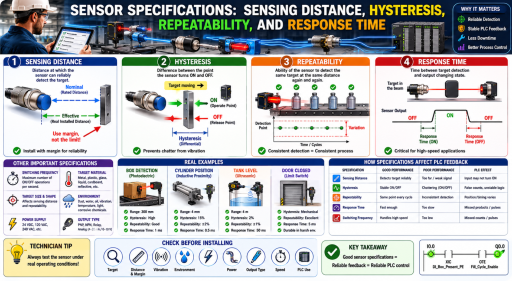
Sensing distance
Hysteresis
Repeatability
Switching frequency
Response time
Target material
Mounting conditions
Environment
These specifications determine whether the sensor will detect the target reliably in the real machine.
A sensor may work perfectly on the bench but fail in production if the target is too far away, moving too fast, vibrating, misaligned, reflective, dirty, or inconsistent.
The Rockwell Automation sensor reference manual explains that when applying a sensor, both nominal sensing distance and effective sensing distance must be evaluated. It also defines hysteresis, repeatability, switching frequency, and response time as important sensor characteristics.
In simple words:
Sensor specifications tell you how reliably the sensor can detect the target in the real application.Why Sensor Specifications Matter
In PLC troubleshooting, technicians often look at the input tag and ask:
Why is the PLC input not turning ON?
Why is the sensor flickering?
Why does the machine randomly stop?
Why does this input chatter?
Why does the counter miss products?
Why does the sensor work sometimes but not always?
Many of these problems are related to sensor specifications.
Example:
The sensor is installed at the edge of its sensing range.
The target vibrates.
The sensor turns ON and OFF rapidly.
The PLC sees unstable feedback.
The logic generates false alarms or unstable machine behavior.
This may not be a PLC program problem.
It may be a sensor application problem.
1. Sensing Distance
What Is Sensing Distance?
Sensing distance is the distance between the sensor and the target at which the sensor can reliably detect the target.
This is one of the first specifications technicians look at, but it is also one of the most misunderstood.
The Rockwell manual explains that there is a difference between nominal sensing distance and effective sensing distance. Nominal sensing distance is the rated operating distance under standardized or average conditions, while effective sensing distance is the real “out of the box” sensing distance achieved in the installed application.
That means:
Nominal sensing distance = datasheet/rated distance
Effective sensing distance = real installed distance
Nominal Sensing Distance
Nominal sensing distance is the rated distance for which the sensor is designed.
Example:
Inductive proximity sensor nominal range: 8 mmThis does not always mean the sensor will reliably detect every target at exactly 8 mm in every application.
The nominal distance is usually based on standard test conditions.
Those conditions may not match the real machine.
Effective Sensing Distance
Effective sensing distance is the actual distance at which the sensor detects the target after installation.
This can be affected by:
Target material
Target size
Target shape
Sensor mounting
Temperature
Vibration
Background material
Power supply stability
Sensor adjustment
Environmental conditions
Example:
A proximity sensor rated for 8 mm may detect steel at close to that range.
But it may detect stainless steel or aluminum at a shorter distance.
Another example:
A photoelectric sensor may detect a cardboard box reliably.
But the same sensor may struggle with a shiny, black, transparent, or reflective target.
Technician Rule
Do not install a sensor at the very edge of its sensing distance.
Better practice:
Leave sensing margin.
Test the sensor under real operating conditions.
Account for vibration, target movement, and misalignment.
Bad application:
Sensor range = 10 mm
Target distance = 10 mm
Better application:
Sensor range = 10 mm
Target distance = 5–7 mm, depending on target and application
The exact margin depends on the sensor type, target, and machine conditions.
2. Hysteresis
What Is Hysteresis?
Hysteresis is the difference between the point where the sensor turns ON and the point where it turns OFF.
In simple terms:
The target may need to move slightly away from the sensor before the sensor turns OFF again.The Rockwell manual defines hysteresis, also called differential travel, as the difference between the operate point and release point when the target is moving away from the sensor face. It also notes that without sufficient hysteresis, a proximity sensor can continuously switch ON and OFF, or “chatter,” when vibration is present.
Simple Example
Imagine a sensor detects a target as it moves closer.
Sensor turns ON at 8 mm.
Sensor turns OFF when target moves away to 9 mm.
The difference is hysteresis.
Hysteresis = 1 mmThis prevents the sensor from rapidly switching ON/OFF if the target is vibrating around the detection point.
Why Hysteresis Matters
Hysteresis helps prevent unstable signals.
Without enough hysteresis, a sensor can chatter:
ON-OFF-ON-OFF-ON-OFFThe PLC may interpret this as:
Multiple parts detected
False counts
Unstable permissive
Fault reset/return cycling
Interlock flickering
Door status changing rapidly
Example:
A metal bracket vibrates near an inductive proximity sensor.
The target is right at the sensing edge.
The input chatters.
The PLC sees the cylinder extended, then not extended, then extended again.
This can cause unstable sequence behavior.
Hysteresis and Debounce
Hysteresis is a sensor/application characteristic.
Debounce is a PLC logic technique.
They are related, but they are not the same.
Hysteresis helps the sensor avoid chatter physically/electronically.
Debounce helps the PLC ignore short unstable transitions.
Good industrial practice uses both ideas when needed.
Example:
Install the sensor with proper sensing margin.
Then use input debounce if the signal is still noisy or mechanically unstable.
Do not use PLC debounce to hide a bad installation if the real issue is sensor distance, alignment, vibration, or target position.
3. Repeatability
What Is Repeatability?
Repeatability is the ability of the sensor to detect the same target at the same distance repeatedly under the same conditions.
The Rockwell manual defines repeatability as the ability of a sensor to detect the same object at the same distance time after time, usually expressed as a percentage of nominal sensing distance and based on constant ambient temperature and supply voltage.
In simple words:
Repeatability tells you how consistent the sensor is.Simple Example
A box passes in front of a photoelectric sensor.
A repeatable sensor detects the box at the same point every time.
Box 1 detected at position A.
Box 2 detected at position A.
Box 3 detected at position A.
Box 4 detected at position A.
Poor repeatability may look like this:
Box 1 detected early.
Box 2 detected late.
Box 3 detected correctly.
Box 4 missed.
This creates inconsistent machine behavior.
Why Repeatability Matters
Repeatability is important when timing, position, or sequence accuracy matters.
Examples:
Counting bottles
Stopping a conveyor at the correct position
Detecting a label registration mark
Confirming cylinder position
Triggering a reject cylinder
Starting a fill cycle
Detecting product at high speed
If repeatability is poor, the PLC logic may still be correct, but the process result will be inconsistent.
Example:
A photoeye detects boxes at different points because box color and reflectivity vary.
The PLC starts the stop timer at different times.
The box stops in slightly different positions.
The filling nozzle is no longer centered.
That is a sensor repeatability/application issue.
4. Switching Frequency
What Is Switching Frequency?
Switching frequency is how many times per second a sensor can switch ON and OFF under specified conditions.
The Rockwell manual describes switching frequency as the number of switching operations per second achievable under standardized conditions. For inductive proximity sensors, it is the maximum speed at which the sensor can deliver discrete pulses as a target enters and leaves the sensing field, and it depends on target size, distance, target speed, and switch type.
In simple words:
Switching frequency tells you how fast the sensor can detect repeated targets.Simple Example
A conveyor has small metal tabs passing by an inductive proximity sensor.
If the tabs pass slowly, the sensor can switch ON and OFF for each tab.
If the tabs pass too fast, the sensor may miss some pulses.
Example:
Target 1 detected
Target 2 detected
Target 3 missed
Target 4 detected
This matters for:
High-speed counting
Speed sensing
Encoder-like pulse detection
Sprocket tooth detection
Bottle counting
Reject timing
Indexing systems
PLC Technician Note
Switching frequency is only one part of the speed problem.
You also need to consider:
Sensor response time
PLC scan time
Input module filter time
High-speed input requirements
Target size
Target spacing
Conveyor speed
Logic execution
A sensor may be fast enough, but the PLC input module or scan may still miss the pulse.
For very fast signals, consider:
High-speed input module
Encoder input
Pulse stretching
Slower mechanical trigger point
Different sensor location
Faster sensor
5. Response Time
What Is Response Time?
Response time is the amount of time between the sensor detecting the target and the sensor output changing state.
The Rockwell manual defines response time as the time that elapses between target detection and the output changing from ON to OFF or OFF to ON. It also notes that response time must be considered relative to the speed at which an object passes through the sensing beam, because extremely fast movement can prevent the sensor from responding quickly enough.
In simple words:
Response time is how fast the sensor reacts.Simple Example
A product passes through a photoelectric sensor beam.
Target enters beam.
Sensor detects target.
After response time, output turns ON.
Target leaves beam.
After response time, output turns OFF.
If the target moves too fast and is in the sensing zone for less time than the sensor needs to react, the output may not switch reliably.
Why Response Time Matters
Response time is critical in applications such as:
High-speed conveyors
Bottle counting
Label detection
Reject systems
Registration marks
Cut-to-length machines
Packaging machines
Small product detection
Fast indexing
Example:
A label passes a photoelectric sensor very quickly.
The sensor response time is too slow.
The PLC never receives a reliable input.
The reject system misses the bad product.
This is not a ladder logic issue.
It is a sensor speed/application issue.
Practical Example: Conveyor Box Detection
Application:
A photoelectric sensor detects boxes on a conveyor.Important specifications:
Sensing distance:
Can the sensor reliably detect the box at the installed distance?

Hysteresis:
Will the signal remain stable if the box vibrates or shifts?

Repeatability:
Will every box be detected at the same point?

Response time:
Is the sensor fast enough for the conveyor speed?
PLC tag:
DI_Box_Present_PEPossible PLC use:
Start fill cycle
Stop conveyor
Count product
Detect jam
Trigger reject
Troubleshooting example:
Symptom:
Box present input flickers.

Possible causes:
Sensor installed at edge of range.
Box is vibrating.
Reflector is dirty.
Photoeye is misaligned.
Target color or reflectivity changes.
Input debounce is missing.
Practical Example: Cylinder Position Proximity Sensor
Application:
An inductive proximity sensor confirms cylinder extended position.Important specifications:
Sensing distance:
Is the metal target close enough?

Hysteresis:
Will vibration cause input chatter?

Repeatability:
Will the cylinder stop in the same position every cycle?

Response time:
Is the sensor fast enough for the cylinder speed?
PLC tag:
DI_Cylinder_Extended_ProxPossible PLC use:
Step complete feedback
Sequence transition
Fault if not extended in time
HMI status
Fault example:
Cylinder_Extend_Command = ON
AND DI_Cylinder_Extended_Prox = OFF
AND Extend_Timer.DN
= Cylinder_Extend_Timeout_Fault
If the sensor flickers because of poor mounting or weak sensing margin, the sequence may become unstable.
Practical Example: Door Limit Feedback
Application:
A limit switch confirms an industrial door is fully closed.Important specifications and application factors:
Mechanical travel:
Does the door reliably actuate the switch?

Hysteresis/differential travel:
Does the switch avoid rapid state change near the actuation point?

Repeatability:
Does the door hit the switch the same way every cycle?

Response time:
Usually less critical for slow doors, but still important for status change timing.
PLC tag:
DI_Door_Closed_LSPossible PLC use:
Machine run permissive
Door state feedback
Auto-close complete status
Close timeout fault
HMI indication
Troubleshooting example:
Symptom:
Door appears closed, but PLC does not show Door Closed.

Possible causes:
Limit switch actuator not fully made.
Mechanical misalignment.
Damaged switch arm.
Ice or debris blocking travel.
Bad cable or connector.
PLC input issue.
How These Specifications Affect PLC Logic
Sensor specifications directly affect PLC logic reliability.
Sensing Distance Affects Input Stability
If a sensor is too far from the target:
Input may never turn ON.
Input may flicker.
Input may work only sometimes.
PLC effect:
Permissive fails.
Sequence does not advance.
False fault occurs.
HMI status is unstable.
Hysteresis Affects Chatter
If hysteresis or mounting margin is poor:
Input chatters near the detection point.PLC effect:
False counts
Timer resets
Faults flicker
Sequence transitions become unstable
Repeatability Affects Process Consistency
If repeatability is poor:
Target is detected at inconsistent positions.PLC effect:
Reject timing varies.
Conveyor stop position varies.
Fill position varies.
Machine cycle becomes inconsistent.
Response Time Affects Fast Detection
If response time is too slow:
Sensor may miss fast-moving targets.PLC effect:
Missed counts
Missed reject triggers
Missed label detection
Incorrect production tracking
Technician Troubleshooting Checklist
When troubleshooting a sensor input, ask:
1. Is the sensor installed within its reliable sensing distance?
2. Is the target at the edge of the sensing range?
3. Does the target material reduce the sensing distance?
4. Is the target vibrating or moving inconsistently?
5. Is the sensor input chattering?
6. Is the sensor repeatable cycle after cycle?
7. Is the target moving too fast for the sensor response time?
8. Is the switching frequency high enough for the application?
9. Is the PLC input filter slowing down the signal?
10. Is the PLC scan time missing short pulses?
11. Is the sensor lens or face dirty?
12. Is the sensor aligned correctly?
13. Is the sensor mounted securely?
14. Is there enough sensing margin?
15. Is debounce needed in PLC logic?
Practical Tag Examples
For discrete sensors:
DI_Box_Present_PE
DI_Door_Open_LS
DI_Door_Closed_LS
DI_Cylinder_Extended_Prox
DI_Cylinder_Retracted_Prox
DI_Label_Detected_PE
DI_Motor_Run_FB
For diagnostic bits:
Box_Present_Debounced
Door_Closed_Stable
Cylinder_Extended_Stable
Label_Detected_OneShot
Sensor_Chatter_Alarm
Input_Stability_Timer
For analog or measured sensors:
AI_Distance_Raw
AI_Distance_Inches
AI_Tank_Level_Raw
AI_Tank_Level_Pct
AI_Line_Pressure_PSI
Recommended PLC Logic Practices
1. Do Not Use Unstable Raw Inputs Everywhere
Better structure:
Raw Input → Input Buffer → Debounce/Validation → Logic UseExample:
Local:1:I.Data.0 → DI_Box_Present_PE → Box_Present_Stable → Fill_EnableThis makes the program easier to troubleshoot.
2. Add Timers for Command vs Feedback Faults
Example:
Command is ON.
Expected feedback does not turn ON within allowed time.
Fault is latched.
Logic concept:
Cylinder_Extend_Command
AND NOT DI_Cylinder_Extended_Prox
TON Cylinder_Extend_Fault_Timer

Cylinder_Extend_Fault_Timer.DN
OTL Cylinder_Extend_Timeout_Fault
3. Use Debounce Only When Needed
Debounce can help with noisy signals, but it should not replace correct installation.
Good order:
Correct sensor selection
Correct mounting
Correct alignment
Correct sensing distance
Then debounce if needed
4. Consider High-Speed Inputs for Fast Pulses
If the sensor detects very fast events:
Do not depend only on normal PLC scan logic.Consider:
High-speed input card
Encoder module
Hardware counter
Pulse stretching
Faster sensor
Input filter adjustment
Common Field Symptoms and Possible Specification Issues
| Symptom | Possible Specification/Application Issue |
|---|---|
| Sensor input flickers | Poor sensing margin, vibration, hysteresis issue |
| Sensor misses product | Response time too slow, target too fast, poor alignment |
| Sensor works only sometimes | Target material, distance, dirty lens, unstable mounting |
| Counter misses parts | Switching frequency too low, PLC input filter, scan time |
| Cylinder feedback flickers | Target near sensing edge, vibration, poor repeatability |
| Door closed status unreliable | Limit switch misalignment, mechanical travel issue |
| Analog value unstable | Noise, bad grounding, poor wiring, wrong input configuration |
Final Thoughts
Sensor specifications are not just datasheet details. They directly affect how reliable the PLC feedback will be in the real machine.
A PLC technician should understand these key specifications:
Sensing distance tells you how far the sensor can detect.
Hysteresis helps prevent chatter.
Repeatability tells you how consistent the detection point is.
Switching frequency tells you how fast the sensor can switch repeatedly.
Response time tells you how fast the sensor reacts.
When sensor feedback is unstable, the PLC logic may appear to be the problem, but the real issue may be sensor selection, mounting, alignment, target behavior, or speed.
A good rule is:
Before blaming the ladder logic, verify the sensor application.Good sensor feedback creates reliable PLC logic.
Poor sensor feedback creates unstable machine behavior.