5. PNP vs NPN Sensors: Sourcing and Sinking Explained (5 of 15)
Introduction
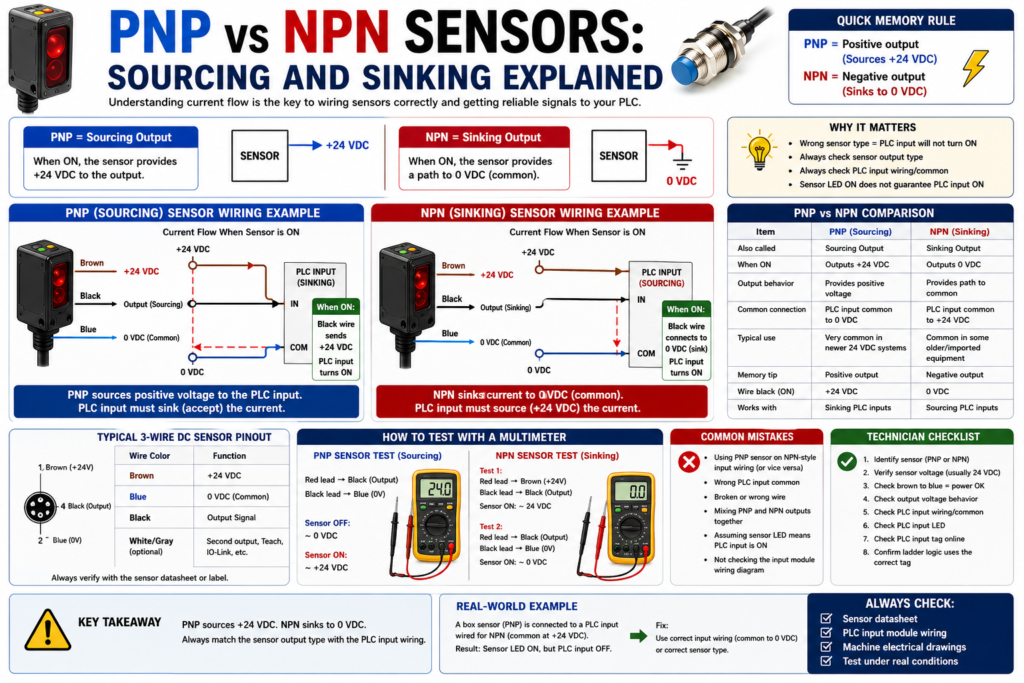
In industrial automation, many DC sensors are either PNP or NPN.
This is one of the most important wiring concepts for PLC technicians to understand because it determines how current flows between the sensor, the PLC input, and the power supply.
A sensor can be the correct type for the application, installed in the correct location, and detecting the target properly, but if the output type does not match the PLC input wiring, the PLC may never receive the signal.
The Rockwell Automation sensor reference manual explains that transistors are typical solid-state output devices for low-voltage DC sensors, and standard transistor outputs come in two types: NPN and PNP. It describes NPN as a sinking output and PNP as a sourcing output.
In simple words:
PNP = sourcing sensor output
NPN = sinking sensor output
But to really understand it, we need to think about current flow.
Why PNP vs NPN Matters
PNP and NPN sensors are usually used with DC control circuits, commonly 24 VDC.
They are very common on:
Photoelectric sensors
Inductive proximity sensors
Capacitive sensors
Ultrasonic sensors
Magnetic sensors
Cylinder position sensors
Machine feedback sensors
A common field problem looks like this:
Sensor has 24 VDC power.
Sensor LED turns ON when target is present.
But PLC input does not turn ON.
Possible reason:
The sensor output type does not match the PLC input wiring.This is why a technician must understand:
Is the sensor PNP or NPN?
Is the PLC input wired for sourcing or sinking?
Where is the common connected?
Where does current flow?
The Simple Concept
The easiest way to understand PNP and NPN is this:
PNP sensor switches +24 VDC to the PLC input.
NPN sensor switches 0 VDC/common to the PLC input.
Another way:
PNP sources positive voltage.
NPN sinks current to negative/common.
PNP Sensor Explained
A PNP sensor is also called a sourcing sensor.
When the sensor turns ON, its output provides positive voltage to the load or PLC input.
Basic idea:
PNP sensor ON = output sends +24 VDCTypical wire colors for a 3-wire DC sensor:
Brown = +24 VDC
Blue = 0 VDC / DC common
Black = sensor output signal
For a PNP sensor:
Brown receives +24 VDC.
Blue receives 0 VDC.
Black sends +24 VDC to the PLC input when the sensor is ON.
Simple current path:
+24 VDC
→ Sensor brown wire
→ Sensor electronics
→ Sensor black output wire
→ PLC input
→ PLC input common
→ 0 VDC
The sensor is sourcing positive voltage to the PLC input.
PNP Example: Box Present Photoeye
Application:
A photoelectric sensor detects a box on a conveyor.Sensor type:
24 VDC PNP photoelectric sensorPLC tag:
DI_Box_Present_PEWhen the box is detected:
Sensor output turns ON.
Black wire sends +24 VDC to PLC input.
PLC input turns ON.
DI_Box_Present_PE = 1.
The PLC can now use that feedback:
DI_Box_Present_PE
AND Fill_Station_Ready
AND No_Faults
= Fill_Cycle_Enable
NPN Sensor Explained
An NPN sensor is also called a sinking sensor.
When the sensor turns ON, its output provides a path to 0 VDC/common.
Basic idea:
NPN sensor ON = output switches to 0 VDC/commonThe Rockwell manual explains that for an NPN transistor output, the load must be connected between the sensor output and the positive power connection, and this is known as a sinking output.
Typical wire colors for a 3-wire DC sensor:
Brown = +24 VDC
Blue = 0 VDC / DC common
Black = sensor output signal
For an NPN sensor:
Brown receives +24 VDC.
Blue receives 0 VDC.
Black provides a path to 0 VDC when the sensor is ON.
Simple current path:
+24 VDC
→ PLC input/common side depending on module wiring
→ PLC input circuit
→ Sensor black output wire
→ Sensor electronics
→ Blue wire
→ 0 VDC
The sensor is sinking current back to common.
NPN Example: Metal Part Proximity Sensor
Application:
An inductive proximity sensor detects a metal target.Sensor type:
24 VDC NPN inductive proximity sensorPLC tag:
DI_Metal_Target_ProxWhen the metal target is detected:
Sensor output turns ON.
Black wire switches toward 0 VDC.
Current flows through the PLC input circuit into the sensor.
PLC input turns ON if wired for that type of input.
Sourcing vs Sinking: The Confusing Part
This is where many people get confused:
A sourcing sensor normally works with a sinking input.
A sinking sensor normally works with a sourcing input.
Why?
Because current must have a complete path.
One side must provide positive voltage, and the other side must provide a path to common.
Think of it like this:
Source = gives current.
Sink = receives current / provides path to common.
So:
PNP sensor = sourcing output
PLC input must accept/sink that current
And:
NPN sensor = sinking output
PLC input must provide/source current
Simple Rule for PLC Technicians
Use this simple memory rule:
PNP = Positive output
NPN = Negative output
More technically:
PNP switches +24 VDC.
NPN switches 0 VDC/common.
This simple rule helps in the field.
3-Wire DC Sensor Wiring
Most PNP and NPN sensors are 3-wire DC sensors.
Typical wiring:
| Wire Color | Function |
|---|---|
| Brown | +24 VDC |
| Blue | 0 VDC / Common |
| Black | Output signal |
Sometimes sensors may also have:
| Wire Color | Function |
|---|---|
| White | Second output, teach input, or complementary output |
| Gray | Teach, IO-Link, or additional function depending on model |
Always verify the datasheet or wiring diagram.
PNP Wiring Concept
For PNP:
Brown → +24 VDC
Blue → 0 VDC
Black → PLC input terminal
PLC input common → 0 VDC
When sensor is ON:
Black wire = +24 VDC
PLC input sees voltage
Input turns ON
Simple visual:
+24 VDC ── Brown
             |
          [PNP Sensor]
             |
Black ───────┘ → PLC Input
PLC Common ───── 0 VDC
Blue ─────────── 0 VDC
NPN Wiring Concept
For NPN:
Brown → +24 VDC
Blue → 0 VDC
Black → PLC input terminal
PLC input common → +24 VDC
When sensor is ON:
Black wire connects the input circuit to 0 VDC
PLC input current flows through sensor to common
Input turns ON
Simple visual:
+24 VDC ───────── PLC Input Common
                  |
               PLC Input
                  |
Black ────────────┘
             |
          [NPN Sensor]
             |
Blue ────────┘ → 0 VDC
Brown ───────── +24 VDC
Important: Always Check the PLC Input Module
Do not assume the PLC input module can accept any sensor.
Check:
Input module type
Wiring diagram
Common terminal
Sinking or sourcing input
Voltage rating
Input current requirement
Input filter time
Terminal assignment
A PNP sensor may work with one input module wiring style but not another.
An NPN sensor may be common in some machines or regions, but it still needs the correct input configuration.
In many modern Allen-Bradley 24 VDC input systems in North America, you will often see PNP/sourcing field devices used with sinking input wiring. But the real answer is always the same:
Check the input module wiring diagram.PNP vs NPN Comparison Table
| Item | PNP Sensor | NPN Sensor |
|---|---|---|
| Common name | Sourcing output | Sinking output |
| Output switches | +24 VDC | 0 VDC / common |
| Simple memory | Positive output | Negative output |
| Typical black wire when ON | +24 VDC | 0 VDC path |
| PLC input style needed | Sinking input | Sourcing input |
| Common field use | Very common in North America | Common in some older/imported equipment |
| Signal type | DC discrete | DC discrete |
How to Test a PNP Sensor with a Meter
Assume a 24 VDC PNP sensor.
Sensor wiring:
Brown = +24 VDC
Blue = 0 VDC
Black = output
Meter test:
Red meter lead → Black output wire
Black meter lead → Blue/common
When sensor is OFF:
You may read 0 VDC or a very small leakage voltage.When sensor is ON:
You should read approximately +24 VDC.That means the PNP output is sourcing positive voltage.
How to Test an NPN Sensor with a Meter
Assume a 24 VDC NPN sensor.
Sensor wiring:
Brown = +24 VDC
Blue = 0 VDC
Black = output
Meter test option:
Red meter lead → Brown/+24 VDC
Black meter lead → Black output wire
When sensor is ON:
You may read approximately 24 VDC across the load path because the black wire is being pulled toward common.Another way is to measure:
Black output wire to Blue/commonWhen NPN is ON:
Black output will be near 0 VDC.When OFF, the output may float depending on the input circuit and meter.
Important:
NPN outputs can be confusing with a meter if the output is not connected to a real input/load.
Always test according to the wiring diagram and machine circuit.
Why the Sensor LED Can Be ON but the PLC Input OFF
This is a very common troubleshooting situation.
Symptom:
Sensor LED turns ON.
PLC input LED stays OFF.
PLC tag remains 0.
Possible causes:
PNP/NPN mismatch
Wrong PLC input common
Broken output wire
Wrong terminal
Bad M12 cable
Bad input channel
Sensor output damaged
Input module not powered
Wrong voltage sensor
2-wire sensor leakage/current issue
PLC tag mapped to wrong input
Very important point:
The sensor LED only proves the sensor detected the target.
It does not prove the PLC received the signal.
A technician must verify:
Sensor power
Sensor output voltage
PLC input terminal voltage
PLC input LED
PLC tag online
PNP/NPN Troubleshooting Path
Use this practical field method:
1. Identify sensor part number.
2. Confirm if sensor is PNP or NPN.
3. Confirm sensor voltage rating.
4. Check brown wire to blue wire for power.
5. Check output wire behavior when sensor turns ON.
6. Check PLC input module wiring diagram.
7. Verify input common polarity.
8. Check PLC input LED.
9. Check PLC input tag online.
10. Confirm the ladder logic uses the correct tag.
Do not jump straight to the ladder logic. First prove the field signal.
Example Problem 1: PNP Sensor Installed on NPN-Style Input Wiring
Situation:
A replacement photoeye was installed.
The sensor LED turns ON when the box is present.
The PLC input does not turn ON.
Investigation:
Old sensor was NPN.
New sensor is PNP.
PLC input common is wired for NPN/sourcing input style.
Result:
The sensor output type does not match the input wiring.Fix:
Install the correct NPN replacement sensor
or
rewire/change module configuration if allowed by design and documentation.
Important:
Never change wiring style without checking drawings, input module type, and machine standards.Example Problem 2: Wrong Common on PLC Input Module
Situation:
PNP sensor output sends +24 VDC to PLC input.
The input still does not turn ON.
Possible issue:
PLC input common is not connected to 0 VDC.For a PNP sourcing sensor, the PLC input circuit usually needs a path back to 0 VDC.
If the input common is missing or wired incorrectly:
No complete circuit
No current flow
PLC input remains OFF
This is why common wiring matters.
Example Problem 3: Mixing PNP and NPN Sensors Together
The Rockwell manual notes that sensors with NPN or PNP transistor outputs can be connected in parallel, but devices must all be of the same output configuration.
That means you should be careful when combining sensor outputs.
Bad practice:
Tie PNP and NPN outputs together on the same input.Possible result:
Short circuit
False signal
Damaged output
Unstable input
Difficult troubleshooting
Better practice:
Use the correct input wiring.
Keep output types consistent.
Use interposing relays or interface modules if needed.
Follow the manufacturer wiring diagram.
2-Wire vs 3-Wire Note
PNP and NPN usually refer to 3-wire DC transistor sensors.
But some sensors are 2-wire.
A 2-wire sensor is wired in series with the load or input circuit. It does not behave exactly like a 3-wire PNP/NPN sensor.
Be careful with 2-wire sensors because they can have:
Voltage drop
Leakage current
Minimum load requirements
Compatibility issues with PLC inputs
For PLC technicians, always check:
Is it 2-wire or 3-wire?
Is it AC or DC?
Is it PNP, NPN, relay, or analog?
PLC Logic Does Not Know PNP or NPN
Inside the PLC program, the logic usually only sees:
Input ON
or
Input OFF
The ladder logic does not care whether the field sensor is PNP or NPN.
Example:
DI_Box_Present_PE = 1The PLC logic uses the tag as a condition:
DI_Box_Present_PE
AND Fill_Station_Ready
= Fill_Enable
PNP vs NPN is mostly a wiring and input module compatibility issue.
However, if the wiring is wrong, the PLC tag will not change correctly, and the logic will not work.
Suggested PLC Tag Names
Good tag names should describe the condition, not the transistor type.
Good examples:
DI_Box_Present_PE
DI_Door_Closed_LS
DI_Cylinder_Extended_Prox
DI_Label_Detected_PE
DI_Motor_Run_FB
DI_Guard_Door_Closed
Avoid:
PNP_Sensor_1
NPN_Input_3
Sensor_A
Input_7
The tag should tell the technician what the signal means.
The wiring documentation or electrical drawing should tell the technician if the device is PNP or NPN.
Quick Field Memory Tips
Use these memory tips:
PNP = Positive output
NPN = Negative output
PNP sources +24 VDC to the input.
NPN sinks the input to 0 VDC.Sensor LED ON does not guarantee PLC input ON.Always check the sensor output type and PLC input common.The circuit must be complete for the PLC input to turn ON.Simple Technician Checklist
Before replacing or troubleshooting a DC sensor, check:
1. What is the sensor part number?
2. Is it PNP, NPN, relay, analog, or IO-Link?
3. Is it 2-wire or 3-wire?
4. What voltage does it require?
5. What does the wiring diagram show?
6. What PLC input module is used?
7. Is the input common wired for this sensor type?
8. Does the sensor LED change state?
9. Does the black output wire change voltage correctly?
10. Does the PLC input LED turn ON?
11. Does the PLC tag change online?
12. Does the ladder logic use the correct input tag?
Practical Example: Troubleshooting in the Field
Problem:
A proximity sensor was replaced on a cylinder.
After replacement, the sensor LED turns ON when the cylinder extends, but the PLC does not see the extended input.
Step-by-step:
1. Check the old sensor part number.
2. Check the new sensor part number.
3. Verify whether both are PNP or NPN.
4. Check brown to blue: should have 24 VDC.
5. Trigger the sensor and measure black output wire.
6. If PNP, black should go to +24 VDC when ON.
7. If NPN, black should switch toward 0 VDC when ON.
8. Check PLC input common.
9. Check PLC input LED.
10. Check the tag online.
Likely finding:
The replacement sensor has the wrong output type.Corrective action:
Install the correct sensor type or correct the input wiring according to the electrical drawings.Final Thoughts
PNP and NPN sensors are not difficult once you understand current flow.
A PNP sensor is a sourcing output. It switches positive voltage to the PLC input.
An NPN sensor is a sinking output. It switches the input path to 0 VDC/common.
The key point is this:
PNP switches positive.
NPN switches negative.
For PLC technicians, the most important thing is not just memorizing the terms. The most important thing is knowing how to troubleshoot the circuit.
When a sensor LED turns ON but the PLC input does not, always check:
Sensor output type
PLC input type
Input common
Output wire voltage
PLC input LED
PLC tag online
Once you understand PNP and NPN, sensor wiring becomes much easier to diagnose in real industrial machines.