6. 2-Wire vs 3-Wire Sensors in PLC Systems (6 of 15)
Introduction
In industrial PLC systems, sensors are commonly wired as either 2-wire or 3-wire devices.
At first, this sounds simple:
2-wire sensor = two wires
3-wire sensor = three wires
But the real difference is not only the number of wires.
The important difference is how the sensor receives power and how it switches the PLC input.
A sensor may be the correct sensing technology, such as photoelectric, inductive, capacitive, or ultrasonic, but if the wiring type is misunderstood, the PLC input may not work correctly.
The Rockwell Automation sensor reference manual explains that 2-wire devices are designed to wire in series with the load, while in a 3-wire configuration, two wires supply power and the third wire switches the load.
In simple words:
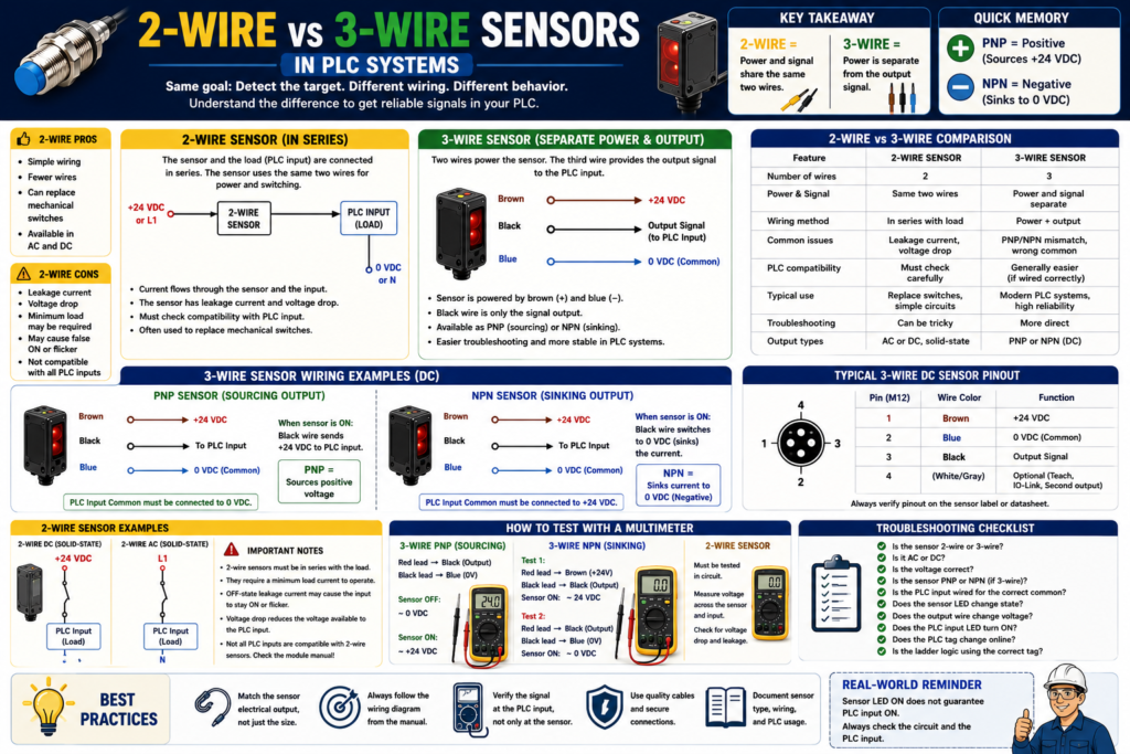
2-wire sensors share power and signal through the same two wires.
3-wire sensors use separate power wires and a separate output signal wire.
Why This Matters for PLC Technicians
A common field problem looks like this:
The sensor LED turns ON.
The PLC input does not turn ON.
Or the PLC input stays partially ON.
Or the input flickers.
Possible causes:
Wrong sensor wiring type
Wrong input module common
Leakage current
Voltage drop
Minimum load issue
PNP/NPN mismatch
Sensor not compatible with PLC input
AC sensor installed where DC input is expected
2-wire sensor leaking enough current to confuse the PLC input
This is why a PLC technician must know the difference between:
2-wire sensor
3-wire sensor
PNP sensor
NPN sensor
Relay output
AC sensor
DC sensor
The sensor type affects wiring, troubleshooting, and PLC input behavior.
What Is a 2-Wire Sensor?
A 2-wire sensor has only two wires.
Those two wires are used for both:
Powering the sensor
Switching the load or PLC input
A 2-wire sensor is usually wired in series with the load.
In PLC applications, the PLC input acts like the load.
Basic concept:
Power Supply → Sensor → PLC Input → Commonor depending on AC/DC circuit style:
Line/Positive → Sensor → Input Load → Neutral/CommonThe key point is this:
A 2-wire sensor must allow some current to pass through the circuit so the sensor electronics can operate.This is why 2-wire sensors can have leakage current.
2-Wire Sensor Simple Diagram
Concept:
+24 VDC or L1
   |
[2-Wire Sensor]
   |
PLC Input
   |
0 VDC or Neutral
When the sensor is OFF, it may still allow a very small amount of current to pass.
When the sensor is ON, it allows more current to pass and the PLC input turns ON.
What Is Leakage Current?
Leakage current is a small amount of current that can flow through a solid-state device even when it is “OFF.”
This is important with 2-wire sensors because the sensor electronics need a small amount of current to stay powered.
Problem:
The sensor is OFF,
but a small current still flows through the PLC input.
Depending on the input module sensitivity, this can cause:
PLC input LED slightly glowing
Input flickering
Input staying ON
False signal
Hard-to-diagnose troubleshooting problem
This is one reason 2-wire sensors must be checked carefully before replacing a sensor or connecting it to a PLC input.
What Is Voltage Drop?
A 2-wire sensor also has voltage drop.
Voltage drop means the sensor uses part of the supply voltage internally.
Example:
Supply voltage = 24 VDC
Sensor voltage drop = 5 VDC
Voltage left for PLC input = about 19 VDC
If the PLC input still has enough voltage and current to turn ON reliably, the circuit may work.
But if the sensor voltage drop is too high, or if several devices are connected in series, the PLC input may not receive enough voltage.
The Rockwell manual explains that 2-wire sensors are easy to wire, but they can limit system performance because they require power from the same line they are switching and have higher voltage drop. It also notes that the practical number of 2-wire sensors connected together is typically limited.
Advantages of 2-Wire Sensors
2-wire sensors can be useful in certain applications.
Advantages:
Simple wiring
Can sometimes replace a mechanical switch
Useful in existing 2-wire circuits
Available in AC and DC versions
Can reduce wire count
Easy concept for basic series circuits
Example:
Old limit switch has two wires.
A 2-wire proximity sensor may be used as an electronic replacement if compatible.
But compatibility must always be checked.
Disadvantages of 2-Wire Sensors
2-wire sensors have limitations that technicians need to understand.
Disadvantages:
Leakage current
Voltage drop
Minimum load requirements
Can be harder to troubleshoot
May not work with all PLC input modules
Can cause false ON states
Limited series connection performance
Sensor electronics depend on current through the load
Important point:
A 2-wire sensor is not just a dry contact.A mechanical limit switch contact may have almost no leakage current when open.
A 2-wire solid-state sensor may still leak current when OFF.
That difference matters.
What Is a 3-Wire Sensor?
A 3-wire sensor has separate wires for power and output.
Most common 3-wire DC sensor colors:
| Wire Color | Function |
|---|---|
| Brown | +24 VDC |
| Blue | 0 VDC / Common |
| Black | Output signal |
Basic concept:
Brown powers the sensor with +24 VDC.
Blue connects to 0 VDC/common.
Black sends the signal to the PLC input.
The Rockwell manual explains that in a 3-wire configuration, two wires supply power and the third switches the load.
3-Wire Sensor Simple Diagram
Brown → +24 VDC
Blue  → 0 VDC
Black → PLC Input
The sensor electronics are powered by brown and blue.
The PLC signal comes from black.
This separation makes 3-wire sensors easier to understand and more reliable in many PLC applications.
3-Wire Sensors: PNP and NPN
Most 3-wire DC sensors are either:
PNP
or
NPN
This connects directly with the previous post.
PNP 3-Wire Sensor
A PNP sensor is a sourcing output.
When ON:
Black wire sends +24 VDC to the PLC input.Typical wiring:
Brown → +24 VDC
Blue  → 0 VDC
Black → PLC input
PLC input common → 0 VDC
Simple memory:
PNP = Positive outputNPN 3-Wire Sensor
An NPN sensor is a sinking output.
When ON:
Black wire provides a path to 0 VDC/common.Typical wiring:
Brown → +24 VDC
Blue  → 0 VDC
Black → PLC input
PLC input common → +24 VDC
Simple memory:
NPN = Negative output2-Wire vs 3-Wire: Main Difference
| Feature | 2-Wire Sensor | 3-Wire Sensor |
|---|---|---|
| Number of wires | 2 | 3 |
| Power and signal | Same two wires | Separate power and output |
| Common DC colors | Varies | Brown, Blue, Black |
| Common issue | Leakage current / voltage drop | PNP/NPN mismatch |
| PLC compatibility | Must check carefully | Usually easier with correct input type |
| Output behavior | Acts in series with input/load | Output switches independently |
| Troubleshooting | Can be trickier | More direct |
| Typical use | Replacing switches, simple circuits | Modern PLC sensor wiring |
Important Concept: 2-Wire Sensor Is Not the Same as 3-Wire PNP/NPN
This is a common misunderstanding.
A 2-wire sensor may be DC or AC, but it does not behave exactly like a standard 3-wire PNP or NPN sensor.
A 3-wire sensor has a dedicated output transistor.
A 2-wire sensor is installed in series and must power itself through the same circuit it switches.
So do not assume:
2-wire DC sensor = PNPor
2-wire DC sensor = NPNAlways check the datasheet.
Example 1: 2-Wire Sensor Replacing a Limit Switch
Application:
A mechanical limit switch has two wires.
Maintenance wants to replace it with an electronic proximity sensor.
Possible issue:
The old limit switch was a dry contact.
The new 2-wire proximity sensor has leakage current and voltage drop.
Result:
PLC input may stay ON.
PLC input may flicker.
PLC input may not turn ON reliably.
Correct approach:
Check sensor voltage rating.
Check AC or DC type.
Check leakage current.
Check voltage drop.
Check PLC input module specifications.
Test the circuit under real conditions.
Example 2: 3-Wire PNP Photoeye on a Conveyor
Application:
A photoelectric sensor detects a box on a conveyor.Sensor:
24 VDC 3-wire PNP photoeyeWiring:
Brown → +24 VDC
Blue  → 0 VDC
Black → PLC input
PLC input common → 0 VDC
When a box is detected:
Black output sends +24 VDC.
PLC input turns ON.
DI_Box_Present_PE = 1.
PLC use:
Box present permissive
Fill cycle enable
Product count
Jam detection
Example 3: 3-Wire NPN Proximity Sensor
Application:
A proximity sensor detects a metal target on a cylinder.Sensor:
24 VDC 3-wire NPN proximity sensorWiring concept:
Brown → +24 VDC
Blue  → 0 VDC
Black → PLC input
PLC input common → +24 VDC
When the target is detected:
Black output switches toward 0 VDC.
PLC input turns ON if the input is wired correctly.
PLC tag:
DI_Cylinder_Extended_ProxExample 4: Sensor LED ON but PLC Input OFF
Problem:
A sensor detects the target.
The sensor LED turns ON.
The PLC input LED does not turn ON.
Possible causes with 2-wire sensors:
Voltage drop too high
Leakage current issue
Minimum load not met
Wrong AC/DC type
Input module not compatible
Wrong wiring
Possible causes with 3-wire sensors:
PNP/NPN mismatch
Wrong input common
Broken black output wire
Wrong terminal
Bad M12 cable
Input module not powered
Wrong sensor voltage
Wrong tag mapping
Important technician rule:
Sensor LED ON only proves the sensor detected the target.
It does not prove the PLC received the signal.
Troubleshooting a 2-Wire Sensor
For a 2-wire sensor, ask:
1. Is the sensor AC or DC?
2. Is it rated for the control voltage?
3. Is it wired in series with the PLC input/load?
4. Does the PLC input module allow this type of sensor?
5. What is the OFF-state leakage current?
6. What is the ON-state voltage drop?
7. Is there a minimum load requirement?
8. Does the PLC input stay ON when the sensor should be OFF?
9. Does the input fail to turn ON when the sensor detects?
10. Is an interposing relay or load resistor needed according to the manufacturer?
Be careful with load resistors or added components. Only use them when approved by the electrical design, manufacturer recommendations, and site standards.
Troubleshooting a 3-Wire Sensor
For a 3-wire sensor, ask:
1. Is brown connected to +24 VDC?
2. Is blue connected to 0 VDC/common?
3. Is black connected to the PLC input?
4. Is the sensor PNP or NPN?
5. Is the PLC input common wired correctly?
6. Does the sensor LED change state?
7. Does the black output wire change voltage?
8. Does the PLC input LED turn ON?
9. Does the PLC tag change online?
10. Is the correct input address/tag used in the logic?
For PNP:
Black wire should provide +24 VDC when ON.For NPN:
Black wire should switch toward 0 VDC/common when ON.How to Test with a Multimeter
3-Wire PNP Sensor
Wires:
Brown = +24 VDC
Blue = 0 VDC
Black = Output
Meter test:
Red lead → Black output
Black lead → Blue/common
Expected:
Sensor OFF ≈ 0 VDC
Sensor ON ≈ +24 VDC
3-Wire NPN Sensor
Meter test option:
Red lead → Brown/+24 VDC
Black lead → Black output
Expected when sensor is ON:
Meter may read approximately 24 VDC because the output is being pulled toward 0 VDC.Another check:
Black output to blue/commonExpected when ON:
Black output near 0 VDCNPN outputs can be confusing if measured without the proper input/load connected, so always use the wiring diagram.
2-Wire Sensor
Testing 2-wire sensors can be trickier because the sensor needs the load/input circuit to operate.
Check:
Voltage across the sensor
Voltage across the PLC input
Current through the circuit
OFF-state leakage
ON-state voltage drop
Do not treat it exactly like a mechanical dry contact.
2-Wire Sensor Field Symptoms
| Symptom | Possible Cause |
|---|---|
| PLC input stays ON when sensor is OFF | Leakage current too high |
| PLC input does not turn ON fully | Voltage drop too high |
| Sensor LED ON but input weak | Not enough load/current |
| Input flickers | Load compatibility or unstable target |
| Sensor works with relay but not PLC input | PLC input too sensitive or incompatible |
| Multiple sensors in series fail | Voltage drops add together |
3-Wire Sensor Field Symptoms
| Symptom | Possible Cause |
|---|---|
| Sensor LED ON, PLC input OFF | PNP/NPN mismatch or wrong common |
| No sensor LED | Missing brown/blue power |
| Output wire does not change | Bad sensor or wrong type |
| PLC input LED ON but tag OFF | Wrong input mapping or program issue |
| Input flickers | Target, alignment, vibration, wiring noise |
| Sensor output damaged | Short circuit or incorrect wiring |
Series and Parallel Connections
2-Wire Sensors in Series
2-wire sensors can be wired in series, but there are limits.
The Rockwell manual notes that because each 2-wire device supplies power to the next device, the response time becomes the sum of the turn-on times for each device, and voltage drop limits the practical number that can be connected together.
In simple words:
More 2-wire sensors in series = more voltage drop and slower response.That can cause unreliable PLC input behavior.
3-Wire Sensors in Parallel
3-wire transistor outputs can often be wired in parallel if they are the same output configuration.
The Rockwell manual notes that sensors with NPN or PNP transistor outputs are straightforward to wire in parallel, but the devices must all be of the same output configuration.
Important:
Do not mix PNP and NPN outputs together.If you need to combine signals, consider proper PLC logic, relays, diode isolation where appropriate, or approved interface modules.
PLC Logic View
Inside the PLC program, the logic usually sees only:
Input ON
Input OFF
The PLC logic does not directly care if the sensor is 2-wire or 3-wire.
Example tag:
DI_Box_Present_PELogic:
DI_Box_Present_PE
AND Fill_Station_Ready
AND No_Faults
= Fill_Enable
But if the wiring is wrong, the tag will not change correctly.
So the real relationship is:
Correct sensor wiring → Reliable PLC input → Reliable ladder logicGood Tag Naming
Do not name tags only by wire type.
Avoid:
Two_Wire_Sensor_1
Three_Wire_Sensor_A
Input_3
Better:
DI_Box_Present_PE
DI_Door_Closed_LS
DI_Cylinder_Extended_Prox
DI_Label_Detected_PE
DI_Air_Pressure_OK
DI_Motor_Run_FB
The tag should describe what the input proves.
The electrical drawing or device list should describe whether it is 2-wire, 3-wire, PNP, NPN, AC, DC, relay, or analog.
Recommended Sensor Documentation Format
Example:
Tag Name:
DI_Box_Present_PE

Sensor Type:
Photoelectric sensor

Wiring Type:
3-wire DC

Output Type:
PNP sourcing

Voltage:
24 VDC

Normal State:
ON when box is present

PLC Input Module:
24 VDC digital input

PLC Use:
Box present permissive for fill cycle

Troubleshooting:
Check brown to blue for 24 VDC, black output to blue for +24 VDC when ON, PLC input LED, and tag online.
Another example:
Tag Name:
DI_Door_Closed_LS

Sensor Type:
2-wire electronic proximity sensor

Wiring Type:
2-wire DC in series with PLC input

Voltage:
24 VDC

Normal State:
ON when door is closed

Important Notes:
Check leakage current and voltage drop compatibility with PLC input module.
Technician Checklist
Before installing or replacing a sensor, ask:
1. Is the sensor 2-wire or 3-wire?
2. Is it AC or DC?
3. What voltage does it require?
4. Is the output PNP, NPN, relay, analog, or IO-Link?
5. What does the wiring diagram show?
6. What PLC input module is used?
7. What is the input common polarity?
8. Is leakage current a concern?
9. Is voltage drop a concern?
10. Is a minimum load required?
11. Does the sensor LED change state?
12. Does the PLC input LED change state?
13. Does the PLC tag change online?
14. Is the ladder logic using the correct input tag?
15. Was the replacement sensor matched by exact electrical output, not only by physical size?
Practical Field Rule
When replacing a sensor, do not match only:
Body size
Connector style
Sensing distance
Brand
Also match:
2-wire or 3-wire
AC or DC
PNP or NPN
Normally open or normally closed
Voltage rating
Output current
Connector pinout
Sensing mode
Environmental rating
A sensor can physically fit perfectly and still be electrically wrong.
Final Thoughts
2-wire and 3-wire sensors are both common in industrial automation, but they are not wired or troubleshot the same way.
A 2-wire sensor uses the same two wires for power and signal. It is wired in series with the load or PLC input. This makes wiring simple, but leakage current, voltage drop, and load compatibility must be considered.
A 3-wire sensor uses two wires for power and one separate wire for the output signal. This is very common in modern 24 VDC PLC systems and is usually easier to troubleshoot, but the technician must still verify PNP/NPN output type and PLC input common wiring.
The key takeaway is:
2-wire sensors share power and signal.
3-wire sensors separate power and signal.
And the field troubleshooting rule is:
Sensor LED ON does not guarantee PLC input ON.
Always verify the output signal at the PLC input.
Understanding this difference helps technicians troubleshoot sensor problems faster and avoid incorrect replacements in real industrial machines.