7. Analog Input Troubleshooting
Is It the Sensor, Wiring, PLC Card, Scaling, or HMI?
Analog input troubleshooting is one of the most valuable skills for an automation technician.
When an HMI value looks wrong, unstable, frozen, too high, too low, or completely missing, the problem is not always the transmitter. It may be in the process, wiring, loop power, analog input card, PLC scaling, HMI tag, or even the instrument range.
In simple terms:
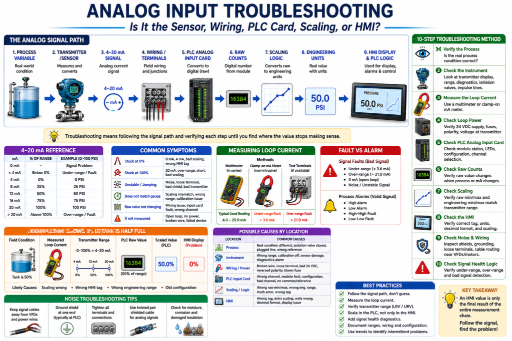
Analog input troubleshooting means following the signal path from the real process to the HMI display until you find where the value stops making sense.
A good technician does not guess. A good technician follows the signal.
The book Lessons In Industrial Instrumentation covers 4–20 mA analog current signals, PLC analog input scaling, loop-powered transmitters, current-loop troubleshooting methods, signal measurement, loop calibrators, and voltage measurements as part of industrial instrumentation troubleshooting.
The Analog Signal Path
A typical analog signal path looks like this:
Process Variable
→ Transmitter / Sensor
→ 4–20 mA Signal
→ Wiring / Terminals
→ PLC Analog Input Card
→ Raw Counts
→ Scaling Logic
→ Engineering Units
→ HMI Display
→ PLC Alarms / Logic
Example:
Tank Level
→ Level Transmitter
→ 4–20 mA
→ Analog Input Channel
→ Raw Value
→ Scaling
→ Tank Level %
→ HMI Display
If the HMI value is wrong, the technician must find which part of the path is wrong.
Common Symptoms
Analog input problems usually show up in one of these ways:
| Symptom | Possible Meaning |
|---|---|
| HMI value stuck at 0% | No signal, 4 mA value, bad scaling, wrong HMI tag |
| HMI value stuck at 100% | 20 mA value, over-range, short, bad scaling |
| HMI value is unstable | Noise, loose terminal, bad shield, bad transmitter, poor grounding |
| HMI value does not match field gauge | Scaling mismatch, transmitter range mismatch, bad calibration |
| PLC raw value does not change | Wiring issue, failed input card, wrong channel, no loop power |
| Correct mA but wrong HMI | Scaling, engineering range, or HMI tag issue |
| 0 mA measured | Open loop, no power, broken wire, failed transmitter |
| Value below 4 mA | Under-range, open loop, transmitter fault |
| Value above 20 mA | Over-range, transmitter fault, wrong range |
Technician Rule: Do Not Start at the HMI Only
The HMI is only the final display.
It is not the source of the measurement.
The HMI may show:
Tank Level = 0%But that does not automatically mean the tank is empty.
It could mean:
- The tank is truly empty.
- The transmitter is reading 4 mA.
- The loop is open.
- The analog input is not reading.
- The scaling is wrong.
- The HMI is pointing to the wrong tag.
The technician should always work backward or forward through the signal path.
Step 1 — Verify the Real Process Condition
Before blaming the PLC or transmitter, verify the actual process.
Ask:
Is the real-world process condition actually what the HMI says?Use available field references:
- Local pressure gauge
- Sight glass
- Tank level indicator
- Field transmitter display
- Manual measurement
- Scale display
- Operator observation
- Mechanical position
- Process condition history
Example:
If the HMI shows:
Tank Level = 0%but the sight glass shows the tank is half full, then the HMI value is probably wrong.
Step 2 — Check the Instrument
The field instrument may be the source of the problem.
Check:
- Is the transmitter powered?
- Is the display alive?
- Is the transmitter showing an error?
- Is the process connection open?
- Is an isolation valve closed?
- Is the impulse line plugged?
- Is the sensor damaged?
- Is the instrument ranged correctly?
- Is the instrument calibrated?
- Is the device in simulation or test mode?
Example
A pressure transmitter may be good electrically but isolated from the process because a valve is closed.
In that case, the PLC may receive a stable signal, but the signal does not represent the real pressure.
Step 3 — Measure the Loop Current
For a 4–20 mA instrument, measuring the loop current is one of the strongest troubleshooting checks.
Typical interpretation:
| Measured Current | Meaning |
|---|---|
| 0 mA | Open loop, no power, broken wire, failed transmitter |
| Less than 4 mA | Under-range or fault |
| 4 mA | Valid low-end process value |
| 12 mA | 50% of range |
| 20 mA | Valid high-end process value |
| Greater than 20 mA | Over-range or fault |
| Unstable mA | Noise, loose terminal, loop power issue, bad transmitter |
Example:
Measured Current = 12 mA
Transmitter Range = 0–100 PSI
Expected Process Value = 50 PSI
If the loop current is correct, the problem may be after the signal: PLC raw input, scaling, or HMI.
Step 4 — Check Loop Power
Many transmitters need 24 VDC loop power.
A bad power supply or blown fuse can kill the loop.
Check:
- 24 VDC supply
- Fuse or circuit protection
- Power supply common
- Correct polarity
- Voltage at transmitter terminals
- Voltage at PLC input terminals
- Loose or corroded terminal blocks
- Junction box wiring
Important
A transmitter may not work correctly if there is not enough voltage available under load.
For example, a loop may appear okay at low current but become unstable near 20 mA because the transmitter does not have enough voltage left to operate. This can happen when loop resistance is too high.
Step 5 — Check the PLC Analog Input Card
Once the field signal is verified, check the PLC side.
Look at:
- Analog input module status
- Channel status
- Channel fault bits
- Input LED or diagnostic LED
- Raw input value
- Module configuration
- Input type: current or voltage
- Wiring polarity
- Channel common/reference
- Correct slot and channel
- Correct controller tag
Example:
Loop current = 12 mA
PLC raw input = not changing
Possible causes:
- Wrong channel
- Failed analog input channel
- Bad wiring to input card
- Analog input configured for voltage instead of current
- Module fault
- Missing input common
- Broken terminal block connection
Step 6 — Check Raw Counts
The PLC analog input card converts the signal into a raw number.
Example:
4 mA  → Raw Min
12 mA → Mid Raw Value
20 mA → Raw Max
If the raw value changes when the loop current changes, the PLC card is reading the signal.
If the raw value does not change, the problem is likely before or at the input card.
Example
Loop current changes from 4 mA to 20 mA
PLC raw value changes correctly
This means the input card is probably reading the signal.
Then check scaling.
Step 7 — Check Scaling
Scaling converts the raw value into engineering units.
Example:
Raw Counts → Scaling → PSIA correct mA signal with a wrong HMI value often means a scaling problem.
Common Scaling Problems
| Problem | Result |
|---|---|
| Wrong raw min/max | Value too high or too low |
| Wrong engineering min/max | HMI value does not match field |
| Wrong transmitter range | Correct mA but wrong displayed value |
| Wrong units | Operator sees wrong engineering unit |
| Wrong output tag | Logic uses old or incorrect value |
| HMI-side scaling conflicts with PLC scaling | Double scaling or wrong display |
Example: Correct Signal, Wrong Scaling
Field condition:
Pressure Gauge = 75 PSIMeasured signal:
Loop Current = 12 mATransmitter range:
0–150 PSI = 4–20 mAThat means:
12 mA = 75 PSIBut the HMI shows:
50 PSIWhy?
PLC scaling may be set incorrectly:
0–100 PSI = 4–20 mASo the transmitter is correct, but the PLC scaling is wrong.
Step 8 — Check the HMI
If the PLC scaled value is correct but the HMI is wrong, check the HMI configuration.
Possible issues:
- HMI points to wrong PLC tag.
- HMI uses old tag.
- HMI has extra scaling.
- Decimal format is wrong.
- Engineering units are wrong.
- Display object is linked to wrong parameter.
- Alarm object uses different tag than display.
- HMI cache or runtime file is outdated.
Example:
PLC Tag AI_PT101_Pressure_PSI = 75 PSI
HMI Display = 50 PSI
This is likely an HMI tag, display, or runtime configuration issue.
Step 9 — Check Signal Noise
Analog signals can become unstable because of electrical noise.
Common causes:
- VFD power cables near analog signal cable
- Poor shield grounding
- Shield grounded at multiple points
- Loose terminals
- Bad analog common/reference
- Damaged cable insulation
- Moisture in junction box
- Poor cable separation
- Inductive or capacitive coupling
- Bad transmitter electronics
The book includes instrumentation connection topics such as signal coupling, cable separation, electric-field decoupling, magnetic-field decoupling, and high-frequency signal cable considerations, which are important when diagnosing unstable analog readings.
Noise Troubleshooting Tips
When the analog value jumps or flickers, check:
Is the raw value unstable or only the scaled value?If the raw value is unstable, the issue may be electrical or signal-related.
If the raw value is stable but the HMI value is unstable, the problem may be scaling, HMI display formatting, or logic.
Field checks:
- Tighten terminals.
- Inspect cable shield.
- Check shield grounding.
- Separate signal cable from VFD/motor power wiring.
- Check for water or corrosion in junction boxes.
- Verify analog input common/reference.
- Check transmitter damping/filter settings.
- Compare transmitter local display to PLC value.
Step 10 — Check Signal Health Logic
A professional PLC program should detect bad analog signals.
Example tags:
AI_PT101_Signal_OK
AI_PT101_UnderRange
AI_PT101_OverRange
AI_PT101_BadSignal
Example logic concept:
IF mA < 3.6 THEN UnderRange_Fault = TRUE
IF mA > 21.0 THEN OverRange_Fault = TRUE
IF mA >= 3.6 AND mA <= 21.0 THEN Signal_OK = TRUE
This prevents the PLC from using an invalid signal as if it were a real process value.
Process Alarm vs Signal Fault
A process alarm and a signal fault are not the same thing.
| Condition | Meaning |
|---|---|
| Low Level Alarm | The process level is low |
| High Pressure Alarm | The process pressure is high |
| Under-range Fault | The signal is below the valid range |
| Over-range Fault | The signal is above the valid range |
| Bad Signal Fault | The PLC cannot trust the analog value |
Example:
Tank Level = 0%
Signal = 4 mA
This may be a valid low-level process condition.
But:
Tank Level = 0%
Signal = 0 mA
This is probably a signal fault, not a valid tank level.
Practical Troubleshooting Example 1
HMI Shows 0%, Tank Is Half Full
Symptom:
HMI Tank Level = 0%
Sight Glass = 50%
Troubleshooting path:
- Check transmitter display.
- Measure loop current.
- Verify 24 VDC loop power.
- Check PLC raw value.
- Check scaling.
- Check HMI tag.
Possible findings:
| Finding | Likely Cause |
|---|---|
| 0 mA | Open loop, no power, broken wire |
| 4 mA | Transmitter seeing low level or wrong range |
| 12 mA | PLC scaling or HMI problem |
| Raw input not changing | PLC input or wiring issue |
| PLC value correct, HMI wrong | HMI tag or display issue |
Practical Troubleshooting Example 2
HMI Value Is Jumping
Symptom:
Pressure value jumps between 40 PSI and 70 PSIPossible causes:
- Real process fluctuation
- Loose signal wire
- Electrical noise
- Shielding problem
- VFD interference
- Bad transmitter
- Bad analog input channel
- Poor grounding/reference
- Incorrect filtering or damping
Troubleshooting path:
- Compare field transmitter display to HMI.
- Check raw analog value.
- Measure loop current.
- Inspect terminals and junction boxes.
- Check cable routing.
- Check shield grounding.
- Check transmitter damping.
- Check analog input filtering.
Practical Troubleshooting Example 3
Correct mA but Wrong HMI Value
Symptom:
Loop Current = 16 mA
Transmitter Range = 0–100 PSI
Expected Value = 75 PSI
HMI = 60 PSI
Possible cause:
Scaling problemCheck:
- Raw input min/max
- Engineering min/max
- Transmitter LRV/URV
- HMI scaling
- HMI tag
- Units and decimal format
Good PLC Tag Structure
A clear tag structure makes analog troubleshooting easier.
Example:
AI_PT101_Raw
AI_PT101_mA
AI_PT101_Pressure_PSI
AI_PT101_Signal_OK
AI_PT101_UnderRange
AI_PT101_OverRange
AI_PT101_BadSignal
PT101_High_Alarm
PT101_HighHigh_Fault
PT101_HMI_Display
This allows the technician to quickly identify:
- Is the input reading?
- Is the signal healthy?
- Is the value scaled?
- Is the process in alarm?
- Is the HMI showing the correct value?
Technician Checklist
Use this checklist when troubleshooting analog inputs:
Field Process
- Verify actual process condition.
- Check local gauge or display.
- Confirm isolation valves are open.
- Check process connections.
- Look for plugged impulse lines or blocked ports.
Instrument
- Check transmitter power.
- Check transmitter display.
- Check instrument range.
- Check diagnostics.
- Check calibration status.
- Confirm correct process variable and units.
Signal
- Measure loop current.
- Check for 0 mA, under-range, over-range, unstable signal.
- Verify wiring polarity.
- Check loop power.
- Inspect terminals and junction boxes.
PLC Input
- Check module/channel status.
- Check raw input value.
- Confirm current/voltage configuration.
- Verify slot and channel.
- Check input common/reference.
Scaling / HMI
- Confirm raw min/max.
- Confirm engineering min/max.
- Confirm LRV/URV.
- Confirm HMI tag.
- Confirm units and decimal places.
- Confirm alarm limits.
Best Practices
1. Always Follow the Signal Path
Process → Instrument → Signal → PLC Input → Scaling → HMIDo not guess.
2. Compare Multiple References
Compare:
- Field gauge
- Transmitter display
- Loop current
- PLC raw value
- PLC scaled value
- HMI display
The point where the values stop matching is usually close to the problem.
3. Keep Scaling in the PLC
When possible, scale analog signals in the PLC so the HMI, alarms, trends, permissives, interlocks, and logic all use the same engineering unit value.
4. Add Signal Health Diagnostics
Do not use analog values blindly.
Use under-range and over-range detection.
5. Document the Loop
Document:
- Instrument tag
- Signal type
- Range
- PLC card and channel
- Scaling values
- HMI tag
- Alarm setpoints
- Calibration information
Good documentation reduces troubleshooting time.
Key Takeaway
Analog input troubleshooting is not about guessing or replacing parts first.
It is about following the signal path.
Process
→ Instrument
→ 4–20 mA Signal
→ PLC Analog Input
→ Raw Counts
→ Scaling
→ HMI Display
→ Logic
If the signal is wrong in the field, troubleshoot the instrument, wiring, or loop power.
If the signal is correct but the PLC value is wrong, troubleshoot the analog input card or channel configuration.
If the PLC value is correct but the HMI is wrong, troubleshoot the HMI tag, scaling, or display configuration.
Final Thoughts
Analog input troubleshooting is one of the skills that separates a parts changer from a real automation technician.
A strong technician understands that an HMI value is only the final result of a complete measurement chain.
When the value looks wrong, follow the path, measure the signal, verify the raw input, confirm the scaling, and then check the HMI.
The professional rule is simple:
Follow the signal, find the problem.