6. VFD Start Sources and Speed References Explained (6 of 19)
Introduction
One of the most common problems when troubleshooting a Variable Frequency Drive is not electrical power, not the motor, and not even a bad drive.
Many times the real issue is this:
The VFD is not listening to the correct command source.A VFD needs two main instructions before it can control a motor correctly:
1. A Start Command
2. A Speed Reference
The start command tells the drive:
Run or StopThe speed reference tells the drive:
How fast to runThese two concepts are related, but they are not the same. A drive can receive the start command from one place and the speed command from another place.
The examples in this post may reference Allen-Bradley PowerFlex parameters, but the same concepts apply to most industrial VFDs, including ABB, Siemens, Yaskawa, Schneider, Danfoss, Mitsubishi, and other drive manufacturers.
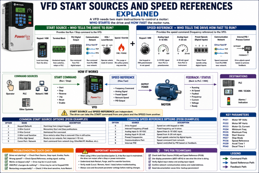
Start Source vs Speed Reference
This is the key concept:
Start Source = Who tells the drive to run?
Speed Reference = Who tells the drive how fast to run?
For example:
Start Source = Terminal Block
Speed Reference = Analog Input
That means a hardwired signal starts the drive, but an analog signal controls the speed.
Another example:
Start Source = Communication Network
Speed Reference = Communication Network
That means the PLC sends both the run command and the speed command over a network.
A PowerFlex 400 example makes this clear: in Auto mode, the start command is defined by P036 [Start Source], while the speed reference is defined by P038 [Speed Reference]. The documentation also explains that Hand mode can use the integral keypad for both start command and speed reference.
1. What Is a Start Source?
The start source is the parameter that tells the VFD where the run command comes from.
The run command may come from:
Keypad / HIM
Terminal block
PLC digital output
Communication network
Hand-Off-Auto mode
Local/Remote selection
Fire/Purge override
Internal drive logic
On a PowerFlex-style drive, this may be configured with:
P036 [Start Source]The PowerFlex documentation describes P036 [Start Source] as the parameter that sets the control scheme used to start the drive. It includes options such as Keypad, 3-Wire, 2-Wire, 2-Wire Level Sensitive, 2-Wire High Speed, and Comm Port.
Common Start Sources
| Start Source | Typical Use |
|---|---|
| Keypad / HIM | Local testing, maintenance, manual operation |
| Terminal Block | Hardwired start/stop from switches, relays, or PLC outputs |
| 2-Wire Control | Maintained run command |
| 3-Wire Control | Momentary start and stop pushbuttons |
| Communication Port | PLC starts/stops the drive over network |
| HOA / Local-Remote | Operator mode selection |
| Purge / Fire Override | Special life-safety or HVAC control mode |
2. Keypad / HIM Start Source
A VFD can usually be started locally using the keypad or HIM.
HIM means:
Human Interface ModuleThis is useful for:
Maintenance
Commissioning
Local testing
Checking motor rotation
Jogging or manual operation
Troubleshooting
On many drives, the local keypad can provide:
Start
Stop
Reverse
Speed adjustment
Fault reset
Parameter access
Status display
The PowerFlex manual explains that the integral keypad Start key is controlled by P036 [Start Source], while the keypad potentiometer is controlled by P038 [Speed Reference]. The Stop key is always active and is controlled by P037 [Stop Mode].
Technician Note
If the drive starts from the keypad but not from the PLC, the drive may not be configured for the correct remote start source.
Check:
[ ] Is the drive in Local or Remote?
[ ] Is Start Source set to Keypad, Terminal Block, or Network?
[ ] Is the PLC output actually energizing the correct VFD input?
[ ] Is the stop input present?
[ ] Is the drive faulted?
[ ] Is an enable input required?
3. Terminal Block Start Source
Terminal block control means the VFD receives hardwired control signals.
These may come from:
Selector switches
Pushbuttons
Control relays
PLC digital outputs
Safety/interlock circuits
HOA switches
Auxiliary contacts
Remote control signals are typically wired into the VFD terminal strip. Digital inputs are ON/OFF signals sent to the VFD and can command functions such as start, stop, reverse, jog, or speed change.
Common Hardwired Commands
| Digital Input Command | Function |
|---|---|
| Run Forward | Starts motor forward |
| Run Reverse | Starts motor reverse |
| Stop | Stops or enables drive depending on wiring/design |
| Jog | Runs at jog speed |
| Fault Reset | Clears fault when active |
| Preset Speed Select | Selects fixed speed |
| Local/Remote | Changes control mode |
| External Fault | Stops/faults drive from external device |
4. 2-Wire Control
In 2-wire control, a maintained contact tells the drive to run.
Example:
Switch closed = Run
Switch open = Stop
This is common with:
PLC output contacts
Maintained selector switches
Relay contacts
Simple run permissive circuits
A basic 2-wire concept:
PLC Output ON  → VFD Run Input ON  → Motor Runs
PLC Output OFF → VFD Run Input OFF → Motor Stops
Important Warning About 2-Wire Control
With some 2-wire level-sensitive modes, if the run command remains active, the drive may restart when a stop condition is removed or after power/fault conditions depending on the configuration.
The PowerFlex documentation warns that when P036 [Start Source] is set to the 2-Wire Level Sensitive option and the Run input is maintained, the Run input does not need to be toggled after a Stop input for the drive to run again. It identifies this as an unintended-operation hazard.
That is why technicians must understand whether the drive requires:
A maintained run signalor:
A new start transition / leading edgeafter a stop, fault, or power cycle.
5. 3-Wire Control
In 3-wire control, the VFD is controlled more like a traditional motor starter circuit.
Typical signals:
Momentary Start PB
Momentary Stop PB
Run Forward / Run Reverse logic
In general:
Start button = momentary command to run
Stop button = opens stop circuit
Drive logic seals in internally
This is common when the drive is controlled by physical pushbuttons instead of a PLC.
2-Wire vs 3-Wire Quick Comparison
| Feature | 2-Wire Control | 3-Wire Control |
|---|---|---|
| Run Command | Maintained | Momentary start |
| Stop Command | Remove run signal | Stop input opens |
| Common Use | PLC output, selector switch | Pushbutton station |
| Restart Behavior | Can restart if run remains active | Often requires new start command |
| Troubleshooting Focus | Check maintained command | Check stop circuit and start pulse |
6. Communication Start Source
A VFD can also be started and stopped by communication.
Common communication methods include:
EtherNet/IP
Modbus RTU
Modbus TCP
PROFIBUS
PROFINET
DeviceNet
RS485 / DSI
CANopen
Vendor-specific networks
On a PowerFlex-style example, the start source may be set to a communication port.
The PowerFlex RS485/DSI documentation states that P036 [Start Source] must be set to RS485/DSI Port if the start command is controlled from the network. It also states that P038 [Speed Reference] must be set to RS485/DSI Port if the speed reference is controlled from the network.
Communication Troubleshooting
If the PLC is supposed to control the VFD over network, verify:
[ ] Correct Start Source
[ ] Correct Speed Reference
[ ] Correct node address / IP address
[ ] Correct data rate
[ ] Correct communication format
[ ] Communication status healthy
[ ] PLC logic is sending run command
[ ] PLC speed reference is scaled correctly
[ ] Drive is not in Local mode
[ ] Communication loss action is understood
The same PowerFlex RS485/DSI section lists communication parameters such as data rate, node address, communication loss action, communication loss time, and communication format.
7. What Is a Speed Reference?
The speed reference tells the VFD how fast to run the motor.
Common speed reference sources include:
Keypad / HIM
Integral potentiometer
External potentiometer
Analog input 0–10 VDC
Analog input 4–20 mA
Preset speeds
Communication network
Internal PID loop
MOP up/down
On a PowerFlex-style drive, this may be configured with:
P038 [Speed Reference]PowerFlex 400 parameter data lists P038 [Speed Reference] options such as Drive Keypad, Internal Frequency, Analog Input 1, Analog Input 2, Preset Frequency, and Communications Port.
Technician Note
A VFD can have a valid run command and still not move the motor if the speed reference is missing or set to zero.
Example:
Start Source = Terminal Block
Speed Reference = Analog Input
Analog Signal = 0 VDC
Result = Drive may run at 0 Hz or minimum frequency
So when troubleshooting, do not only ask:
Is the drive commanded to run?Also ask:
What speed is the drive being commanded to run?8. Keypad / HIM Speed Reference
A technician may use the keypad or HIM to adjust speed locally.
This is useful during:
Startup
Motor rotation test
Maintenance
Manual operation
Temporary troubleshooting
Local control
However, keypad speed control may not be the normal production mode.
A common issue is when the drive was left in local/keypad speed reference after maintenance, and the PLC/HMI speed command no longer controls the motor.
Field Example
Problem:
Operator changes speed from HMI, but motor speed does not change.Possible cause:
Speed Reference is set to Keypad instead of Analog Input or Network.9. Analog Speed Reference
Analog speed references are very common in industrial applications.
Typical signals:
0–10 VDC
4–20 mA
0–20 mA
±10 VDC
Analog inputs are proportional or modulating signals sent to the VFD. These signals can tell the drive what the reference speed should be or provide feedback signal information.
Analog Input Examples
| Signal | Meaning |
|---|---|
| 0 VDC | Minimum speed |
| 10 VDC | Maximum speed |
| 4 mA | Minimum speed |
| 20 mA | Maximum speed |
| 12 mA | Approximately mid-range speed |
Example:
4–20 mA = 0–60 HzThen:
4 mA  = 0 Hz
12 mA = 30 Hz
20 mA = 60 Hz
Analog Troubleshooting Checks
If the speed is wrong, check:
[ ] Is the drive configured for voltage or current?
[ ] Is the analog signal present?
[ ] Is the polarity correct?
[ ] Is analog common correct?
[ ] Is scaling correct?
[ ] Is minimum/maximum frequency correct?
[ ] Is the PLC analog output scaled correctly?
[ ] Is the shield grounded correctly?
[ ] Is signal noise present?
PowerFlex 400 documentation shows analog inputs that are DIP-switch selectable for voltage or current and analog outputs that can be selected for voltage or current.
10. Preset Speed Reference
Preset speeds are fixed speed values stored in the drive.
They are usually selected using digital inputs.
Example:
Input 1 OFF, Input 2 OFF = Speed 1
Input 1 ON,  Input 2 OFF = Speed 2
Input 1 OFF, Input 2 ON  = Speed 3
Input 1 ON,  Input 2 ON  = Speed 4
Preset speeds are useful when a machine only needs a few specific speeds.
Applications:
Conveyors
Mixers
Indexing equipment
Fans
Simple machine modes
Batch processes
The PowerFlex manual notes that digital inputs can have priority for frequency control when programmed as preset speeds and active.
11. Internal PID Speed Reference
Some VFDs can generate their own speed command using an internal PID loop.
In this case, the drive compares:
Setpoint vs FeedbackThen adjusts motor speed automatically.
Common applications:
Pressure control
Flow control
Tank level control
Temperature-related air movement
Fan static pressure
Pump pressure
Example:
Pressure Setpoint = 60 PSI
Pressure Feedback = 52 PSI
VFD increases speed
This is common in pump and fan applications.
12. Hand-Off-Auto, Local/Remote, and Auto/Manual Modes
Many VFD systems include control mode selection.
Common modes:
| Mode | Typical Meaning |
|---|---|
| Hand | Local keypad or local panel control |
| Off | Drive stopped or disabled |
| Auto | PLC, process controller, or external system controls drive |
| Local | Control from drive/keypad/local station |
| Remote | Control from PLC, terminal block, or network |
| Manual | Operator manually controls speed |
| Auto | Speed is controlled automatically by process/PID |
PowerFlex 400 documentation describes configurable Hand-Off-Auto, Local/Remote, and Auto/Manual configurations. In Hand or Local operation, command and speed may come from the keypad; in Auto or Remote operation, start and speed are defined by parameters such as Start Source and Speed Reference.
Technician Note
When troubleshooting, always check mode first.
Ask:
Is the drive in Hand, Off, or Auto?
Is the drive in Local or Remote?
Is the drive in Manual or Auto?
Is the operator expecting HMI control while the drive is in Local?
Many “VFD not responding” problems are actually mode-selection problems.
13. Drive Feedback: How the VFD Reports Back
The VFD does not only receive commands. It also sends feedback.
Common feedback signals:
Drive Running
Drive Ready
Drive Faulted
At Speed
Output Frequency
Output Current
Output Voltage
DC Bus Voltage
Motor Overload
Communication Status
Feedback may be sent through:
Relay outputs
Digital outputs
Analog outputs
Network communication
HIM/keypad display
PowerFlex 400 documentation lists programmable relay outputs and opto outputs that can indicate drive or motor conditions, and analog outputs that can be used for metering.
Command vs Feedback
This distinction is very important:
Command = What the PLC or operator requests
Feedback = What the drive/motor is actually doing
Example:
VFD_Start_Cmd = ON
VFD_Running_FB = OFF
VFD_Faulted = ON
That means the PLC is requesting the drive to run, but the drive is not running because it is faulted.
14. Common Troubleshooting Scenarios
Scenario 1: Drive Runs from Keypad but Not from PLC
Possible causes:
[ ] Start Source set to Keypad instead of Terminal Block or Network
[ ] Drive is in Local mode
[ ] PLC output not energizing
[ ] Stop input missing
[ ] Enable input missing
[ ] Source/sink wiring mismatch
[ ] Digital input assigned wrong function
Scenario 2: Drive Starts but Motor Does Not Speed Up
Possible causes:
[ ] Speed Reference set to wrong source
[ ] Analog signal missing
[ ] Network speed reference not being written
[ ] Minimum frequency set to 0
[ ] Preset speed selected incorrectly
[ ] PID output at minimum
[ ] Drive current limiting
Scenario 3: HMI Speed Command Does Nothing
Possible causes:
[ ] Drive is in Hand/Local mode
[ ] Speed Reference set to Keypad
[ ] PLC analog output not changing
[ ] Network reference not enabled
[ ] Analog input configured for wrong signal type
[ ] Scaling issue in PLC or VFD
Scenario 4: Drive Restarts Unexpectedly
Possible causes:
[ ] 2-wire maintained run command still active
[ ] Auto restart enabled
[ ] Stop condition removed while run is maintained
[ ] Fire/Purge override active
[ ] Network command still active
[ ] HOA selector in Auto with active PLC command
15. Good PLC Tag Names for VFD Control
For a PLC-controlled VFD, clear tag names help a lot.
Example command tags:
VFD_Start_Cmd
VFD_Stop_Cmd
VFD_Reset_Cmd
VFD_Reverse_Cmd
VFD_Speed_Ref
VFD_PresetSpeed1_Cmd
VFD_PresetSpeed2_Cmd
Example feedback tags:
VFD_Ready_FB
VFD_Running_FB
VFD_AtSpeed_FB
VFD_Faulted_FB
VFD_OutputFreq_FB
VFD_OutputCurrent_FB
VFD_CommOK_FB
Example status tags:
VFD_LocalMode
VFD_RemoteMode
VFD_AutoMode
VFD_HandMode
VFD_SpeedRef_Active
16. Technician Checklist: Start Source and Speed Reference
Use this checklist when a VFD does not respond correctly:
[ ] Is the drive powered and ready?
[ ] Is the drive faulted?
[ ] Is the drive in Local or Remote?
[ ] Is HOA mode correct?
[ ] Is Start Source set correctly?
[ ] Is Speed Reference set correctly?
[ ] Is the Stop input present?
[ ] Is the Enable input present, if required?
[ ] Is the PLC run command reaching the drive?
[ ] Is the speed reference present?
[ ] Is the analog signal voltage/current correct?
[ ] Is the network command active?
[ ] Is the network speed reference being written?
[ ] Are digital inputs assigned correctly?
[ ] Are preset speed inputs active?
[ ] Is a safety or external fault input active?
[ ] Is a Purge/Fire override active?
Common Mistakes Technicians Should Avoid
[ ] Confusing Start Source with Speed Reference
[ ] Assuming the HMI controls speed when the drive is in Local
[ ] Setting Start Source to Terminal Block but expecting network control
[ ] Setting Speed Reference to Keypad but expecting analog control
[ ] Not checking the Stop input
[ ] Ignoring source/sink wiring
[ ] Forgetting preset speed inputs can override normal reference
[ ] Not checking analog input DIP switch or signal type
[ ] Replacing a drive without recording P036/P038 or equivalent settings
[ ] Resetting faults without understanding why the drive stopped
Simple Technician Explanation
A simple way to explain this topic is:
The Start Source tells the VFD who has permission to start the motor.
The Speed Reference tells the VFD how fast the motor should run.
Or even shorter:
Start Source = Run command
Speed Reference = Speed command
If either one is wrong, the drive may not behave the way the operator or PLC expects.
Final Thoughts
Understanding start sources and speed references is one of the most practical VFD troubleshooting skills.
When a drive does not start, does not respond to the HMI, runs at the wrong speed, or only works from the keypad, do not immediately assume the drive is bad.
First ask:
Who is supposed to start the drive?
Who is supposed to control speed?
Is the drive configured to listen to that source?
Is the correct signal actually reaching the drive?
What feedback is the drive giving back?
A VFD is only going to follow the source that it is configured to follow.
That means good troubleshooting starts with understanding:
Command source
Speed reference
Control mode
Feedback status
Once those are clear, VFD troubleshooting becomes much more logical and much less confusing.