5. Basic VFD Parameters Every Technician Should Understand (5 of 19)
Introduction
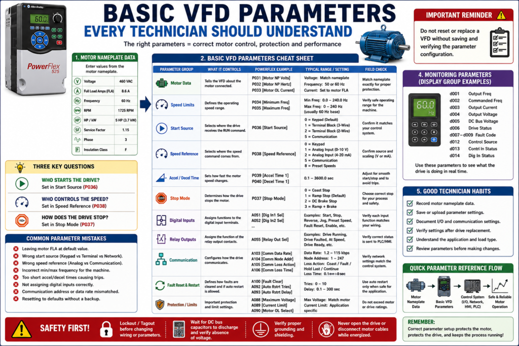
A Variable Frequency Drive can have hundreds of parameters, but an automation technician does not need to memorize every parameter to troubleshoot or commission a drive effectively.
What a technician needs first is to understand the core parameter groups that define how the VFD controls the motor and how it communicates with the machine.
These basic parameters answer important questions:
What motor is connected to the drive?
Where does the start command come from?
Where does the speed reference come from?
How fast is the motor allowed to run?
How quickly should the motor accelerate?
How should the motor stop?
What do the digital inputs do?
What do the relay outputs indicate?
How does the drive communicate with the PLC or HMI?
The examples in this post may reference Allen-Bradley PowerFlex parameters, but the same concepts apply to most industrial VFDs, including ABB, Siemens, Yaskawa, Schneider, Danfoss, Mitsubishi, and other drive manufacturers.
A PowerFlex 4 manual, for example, organizes parameters into groups such as Display Group, Basic Program Group, and Advanced Program Group, and shows parameter naming conventions like P031 [Motor NP Volts], where the number, name, and group help identify the parameter function.
1. Motor Nameplate Parameters
The first group of parameters tells the VFD what motor it is controlling.
These values should come from the motor nameplate.
Common motor data parameters include:
| Parameter Concept | Purpose |
|---|---|
| Motor Rated Voltage | Matches the VFD output to the motor voltage |
| Motor Rated Current / FLA | Sets motor overload protection |
| Motor Rated Frequency | Defines base frequency, usually 50 or 60 Hz |
| Motor Rated RPM | Helps with speed calculation and motor model |
| Motor HP / kW | Used for sizing and application verification |
PowerFlex-style examples:
P031 [Motor NP Volts]
P032 [Motor NP Hertz]
P033 [Motor OL Current]
The PowerFlex parameter cross-reference lists Motor NP Volts, Motor NP Hertz, and Motor OL Current as Basic Program parameters.
Why These Parameters Matter
If motor data is wrong, the VFD may still run the motor, but it may not protect it correctly.
Wrong motor data can cause:
[ ] Motor overload trips
[ ] Overcurrent faults
[ ] Motor heating
[ ] Poor torque
[ ] Failed acceleration
[ ] Incorrect speed behavior
[ ] Weak low-speed performance
Technician Note
Do not set motor current based only on the drive size.
Set the motor overload/current parameter based on the motor nameplate FLA, unless the application or manufacturer procedure requires something different.
2. Minimum Frequency
The minimum frequency parameter defines the lowest speed the drive is allowed to output during normal operation.
PowerFlex-style example:
P034 [Minimum Freq]The PowerFlex parameter cross-reference lists Minimum Freq P034 as a Basic Program parameter.
Example
If minimum frequency is set to:
P034 = 10 HzThen the VFD will not normally run below 10 Hz when commanded to run.
Why Minimum Frequency Matters
Minimum frequency affects:
[ ] Low-speed motor cooling
[ ] Pump or fan minimum flow
[ ] Conveyor minimum movement
[ ] Process stability
[ ] Mechanical lubrication
[ ] Motor torque at low speed
For example, a motor with a shaft-mounted cooling fan may not cool well at very low speed. Running too slowly for too long may cause overheating depending on the motor and load.
3. Maximum Frequency
The maximum frequency parameter defines the highest speed the drive is allowed to output.
PowerFlex-style example:
P035 [Maximum Freq]The PowerFlex parameter cross-reference lists Maximum Freq P035 as a Basic Program parameter.
Example
If maximum frequency is set to:
P035 = 60 HzThen the VFD will not normally command the motor above 60 Hz.
Why Maximum Frequency Matters
Maximum frequency protects the motor and machine from overspeed.
Running above base speed may affect:
[ ] Motor torque
[ ] Pump pressure
[ ] Fan speed
[ ] Conveyor speed
[ ] Gearbox limits
[ ] Bearing speed
[ ] Coupling limits
[ ] Machine safety
Technician Warning
Do not increase maximum frequency just because the operator wants more production.
Higher speed may damage the motor, pump, fan, belt, gearbox, or process equipment.
4. Start Source
The start source parameter tells the VFD where the run command comes from.
Common start sources include:
| Start Source | Description |
|---|---|
| Keypad / HIM | Operator starts the drive locally |
| Terminal Block | Start command comes from hardwired inputs |
| PLC Digital Output | PLC energizes a VFD input |
| Communication Network | PLC sends command over Ethernet/IP, Modbus, Profibus, etc. |
| Internal Logic | Drive starts based on internal function or mode |
PowerFlex-style example:
P036 [Start Source]The PowerFlex parameter cross-reference lists Start Source P036 as a Basic Program parameter.
Why Start Source Matters
A very common troubleshooting issue is:
The drive is healthy, but it will not start.One of the first things to verify is:
Is the drive listening to the correct start source?Example:
| Situation | Problem |
|---|---|
| PLC output is ON, but Start Source is set to Keypad | Drive ignores PLC command |
| HIM start button is pressed, but Start Source is set to Terminal Block | Drive ignores local command |
| Network command is active, but Start Source is not set to communication | Drive ignores network command |
The PowerFlex 400 documentation explains that in Auto mode, the start command is defined by P036 [Start Source], while the speed reference is defined separately by P038 [Speed Reference].
5. Speed Reference
The speed reference parameter tells the VFD where the speed command comes from.
Common speed references include:
| Speed Reference | Example |
|---|---|
| Keypad / HIM | Technician changes speed locally |
| Potentiometer | 0–10 VDC speed pot |
| Analog Input | 0–10 VDC or 4–20 mA from PLC/instrument |
| Preset Speed | Fixed speed selected by digital inputs |
| Communication Network | PLC sends speed command over network |
| Internal PID | Drive adjusts speed based on feedback |
PowerFlex-style example:
P038 [Speed Reference]The PowerFlex parameter cross-reference lists Speed Reference P038 as a Basic Program parameter.
Start Source vs Speed Reference
These two parameters are different.
Start Source = Who tells the drive to run?
Speed Reference = Who tells the drive how fast to run?
Example:
Start Source = Terminal Block
Speed Reference = Analog Input 4–20 mA
That means the drive starts from a hardwired input, but its speed comes from an analog signal.
Another example:
Start Source = Network
Speed Reference = Network
That means the PLC controls both run command and speed over communication.
6. Stop Mode
The stop mode parameter defines how the motor stops when the VFD receives a stop command.
PowerFlex-style example:
P037 [Stop Mode]The PowerFlex parameter cross-reference lists Stop Mode P037 as a Basic Program parameter.
Common Stop Modes
| Stop Mode | Description |
|---|---|
| Coast Stop | Drive output is removed and motor coasts |
| Ramp Stop | Drive decelerates motor using programmed decel time |
| DC Brake Stop | Drive applies DC braking at stop |
| Ramp + Brake | Drive ramps down and may apply braking |
| Safe Torque Off | Safety-rated torque removal, if supported by drive |
Why Stop Mode Matters
Stop mode affects:
[ ] Safety behavior
[ ] Stopping distance
[ ] Mechanical stress
[ ] Deceleration faults
[ ] Overvoltage faults
[ ] Process control
[ ] Operator expectations
For example, a fan or high-inertia load may fault on overvoltage if the deceleration is too aggressive and braking is not properly designed.
7. Acceleration Time
Acceleration time controls how long the drive takes to ramp from low speed to commanded speed.
PowerFlex-style example:
P039 [Accel Time 1]The PowerFlex parameter cross-reference lists Accel Time 1 P039 as a Basic Program parameter.
Example
Accel Time = 10 secondsThe motor will ramp smoothly up to the target speed instead of trying to reach full speed instantly.
Why Acceleration Time Matters
Acceleration time affects:
[ ] Starting current
[ ] Mechanical shock
[ ] Belt stress
[ ] Coupling stress
[ ] Process stability
[ ] Ability to start heavy loads
If acceleration time is too short, the drive may trip on overcurrent or fail to accelerate the motor.
8. Deceleration Time
Deceleration time controls how long the drive takes to ramp the motor down.
PowerFlex-style example:
P040 [Decel Time 1]The PowerFlex parameter cross-reference lists Decel Time 1 P040 as a Basic Program parameter.
Example
Decel Time = 15 secondsThe drive reduces speed gradually over 15 seconds.
Why Deceleration Time Matters
Deceleration time affects:
[ ] Stopping time
[ ] Overvoltage faults
[ ] Regeneration
[ ] Braking resistor requirements
[ ] Product handling
[ ] Machine sequence timing
If deceleration is too short, the motor/load can push energy back into the DC bus, causing overvoltage faults.
9. Reset to Defaults
Most VFDs include a parameter or function that returns the drive to factory default settings.
PowerFlex-style example:
P041 [Reset To Defaults]The PowerFlex parameter cross-reference lists Reset To Defaults P041 as a Basic Program parameter.
Technician Warning
Factory default does not mean application-ready.
After resetting a VFD to defaults, the drive may lose:
[ ] Motor nameplate data
[ ] Start source
[ ] Speed reference
[ ] Accel/decel settings
[ ] Digital input assignments
[ ] Relay output assignments
[ ] Communication settings
[ ] PID settings
[ ] Fault response settings
Never reset a drive to defaults unless you have a backup, parameter list, or clear commissioning plan.
10. Digital Input Parameters
Digital input parameters define what each hardwired input does.
Common digital input functions include:
Start
Stop
Run Forward
Run Reverse
Jog
Preset Speed Select
Fault Reset
Local/Remote
External Fault
Enable
Purge
PowerFlex-style examples:
A051 [Digital In1 Sel]
A052 [Digital In2 Sel]
The PowerFlex parameter cross-reference lists Digital Inx Sel A051/A052 as Advanced Program parameters.
Why Digital Input Parameters Matter
A drive may be wired correctly but still not work if the input parameter is wrong.
Example:
A PLC output is wired to Digital Input 1.
The technician expects it to reset faults.
But Digital Input 1 is configured as Reverse.
That is not a wiring issue. That is a parameter issue.
11. Relay Output Parameters
Relay output parameters define what the VFD output contacts indicate.
Common relay output functions include:
Drive Running
Drive Faulted
Drive Ready
At Speed
Motor Running
Frequency Reached
Alarm
Overload Warning
PowerFlex-style example:
A055 [Relay Out Sel]The PowerFlex parameter cross-reference lists Relay Out Sel A055 as an Advanced Program parameter.
Why Relay Output Parameters Matter
Relay outputs are often wired back to a PLC or HMI.
If the relay output is configured incorrectly, the PLC may show the wrong status.
Example:
The HMI says “Motor Running”
but the relay is actually configured for “Drive Ready.”
That can create operator confusion and bad troubleshooting.
12. Analog Input Parameters
Analog input parameters define how the drive interprets analog signals.
Common analog inputs:
0–10 VDC
4–20 mA
0–20 mA
Potentiometer input
Process feedback
The PowerFlex 400 documentation shows analog input and output capability, including selectable voltage/current input options and analog outputs that can be used for metering or as a speed reference for another drive.
Why Analog Input Parameters Matter
Analog parameters affect:
[ ] Speed reference scaling
[ ] Minimum speed
[ ] Maximum speed
[ ] Signal loss behavior
[ ] PID feedback
[ ] PLC-to-drive speed command
Example:
PLC sends 4–20 mA speed reference.
Drive input is configured for 0–10 VDC.
Result: speed reference does not behave correctly.
13. Display Parameters
Display parameters are read-only or monitoring values that help the technician understand what the drive is doing.
Common display values:
Output Frequency
Commanded Frequency
Output Current
Output Voltage
DC Bus Voltage
Drive Status
Control Source
Digital Input Status
Fault Code
Drive Temperature
Communication Status
PowerFlex-style examples:
d001 [Output Freq]
d002 [Commanded Freq]
d003 [Output Current]
d005 [DC Bus Voltage]
d006 [Drive Status]
d012 [Control Source]
d013 [Contrl In Status]
d014 [Dig In Status]
d007–d009 [Fault x Code]
These are listed in the PowerFlex parameter cross-reference as Display Group parameters.
Technician Note
Display parameters are excellent for troubleshooting because they show what the drive is actually seeing.
For example:
PLC says Start command is ON.
Drive Digital Input Status says input is OFF.
That points you toward a wiring, common, source/sink, or input configuration issue.
14. Communication Parameters
Communication parameters define how the VFD talks to a PLC, HMI, or software tool.
Common communication parameters include:
Protocol
Node address
IP address
Baud rate
Data rate
Communication format
Communication loss action
Communication timeout
PowerFlex-style examples:
A103 [Comm Data Rate]
A104 [Comm Node Addr]
A105 [Comm Loss Action]
A106 [Comm Loss Time]
A107 [Comm Format]
The PowerFlex RS485/DSI documentation notes that P036 [Start Source] must be set to RS485/DSI if the network controls start commands, and P038 [Speed Reference] must be set to RS485/DSI if the network controls speed reference. It also lists communication parameters for data rate, node address, communication loss action, communication loss time, and communication format.
Why Communication Parameters Matter
If communication parameters are wrong, the drive may:
[ ] Not appear online
[ ] Ignore PLC commands
[ ] Show communication loss
[ ] Run from local mode only
[ ] Use the wrong speed reference
[ ] Fail to send status to HMI
Communication settings are especially important when replacing a drive.
15. Fault Reset and Auto-Restart Parameters
Many VFDs include parameters for fault clearing and auto restart.
PowerFlex-style examples:
A092 [Auto Rstrt Tries]
A093 [Auto Rstrt Delay]
A100 [Fault Clear]
Auto Restart can automatically reset certain faults and attempt to restart the drive, but warns that caution is required because the drive may issue its own start command based on user-selected programming.
Technician Warning
Auto restart can be useful in some applications, but it can also be dangerous if technicians or operators are not aware of it.
Always verify:
[ ] Is auto restart enabled?
[ ] What faults can auto reset?
[ ] How many attempts are allowed?
[ ] What is the delay time?
[ ] Is the machine safe to restart automatically?
[ ] Does the HMI clearly show auto restart status?
16. Programming Lock / Parameter Protection
Some drives include a parameter lock or password function to prevent unauthorized changes.
PowerFlex-style example:
A101 [Program Lock]The PowerFlex parameter cross-reference lists Program Lock A101 as an Advanced Program parameter.
Why Parameter Protection Matters
In a plant environment, accidental parameter changes can create serious issues.
Parameter protection helps prevent:
[ ] Wrong start source
[ ] Wrong speed reference
[ ] Wrong max speed
[ ] Changed accel/decel time
[ ] Disabled reverse protection
[ ] Incorrect communication settings
[ ] Unexpected machine behavior
17. Backup and Documentation Parameters
A technician should treat parameters as part of the machine’s control system documentation.
Before replacing or changing a VFD:
[ ] Upload the parameter file if software is available
[ ] Save or print the parameter list
[ ] Take pictures of critical parameter screens
[ ] Record motor nameplate data
[ ] Record communication settings
[ ] Record I/O configuration
[ ] Record fault history
PowerFlex 400 documentation states that DriveExplorer can save, restore, print, compare, edit, upload, and download parameters, while DriveTools SP supports online and offline programming with parameter editing and visual status indication.
Basic Parameter Cheat Sheet
| Parameter Group | What It Answers | PowerFlex Example |
|---|---|---|
| Motor Data | What motor is connected? | P031, P032, P033 |
| Speed Limits | How slow/fast can it run? | P034, P035 |
| Command Source | Who starts the drive? | P036 |
| Stop Behavior | How does it stop? | P037 |
| Speed Reference | Who controls speed? | P038 |
| Ramps | How fast does it accel/decel? | P039, P040 |
| Digital Inputs | What do the input terminals do? | A051, A052 |
| Relay Outputs | What status is sent out? | A055 |
| Communication | How does it talk to PLC/HMI? | A103–A107 |
| Fault Reset | How are faults cleared? | A092, A093, A100 |
| Monitoring | What is the drive doing now? | d001–d014 |
Example: Common Field Scenario
Problem
A VFD was replaced, but now the motor will not start from the PLC.
Possible Parameter Issues
[ ] Start Source is set to Keypad instead of Terminal Block or Network
[ ] Stop input is not configured correctly
[ ] Digital input is assigned to the wrong function
[ ] Drive is in Local mode instead of Remote/Auto mode
[ ] Communication node address is wrong
[ ] Speed Reference is missing
[ ] Minimum frequency is set incorrectly
[ ] Fault reset or enable input is not present
The VFD may be electrically healthy, but the parameter setup may not match the application.
Example: Motor Runs but at Wrong Speed
Possible Causes
[ ] Speed Reference set to Keypad instead of Analog Input
[ ] Analog input type set to voltage instead of current
[ ] Min/max frequency scaling incorrect
[ ] Preset speed selected by digital input
[ ] PLC analog output scaling incorrect
[ ] Communication reference not enabled
[ ] Drive is in local/manual mode
This is why start source and speed reference must always be checked separately.
Technician Notes
1. Do Not Guess Parameters
Use the manual, backup file, old drive, HIM copy, or documented parameter list.
2. Start Source and Speed Reference Are Different
A drive can start from one source and receive speed from another.
3. Defaults Are Not Application Settings
Factory defaults are only a starting point.
4. Display Parameters Are Your Best Friend
They show what the drive actually sees.
5. Always Save Before Changing
Before modifying a parameter, document the existing value.
Field Checklist: Basic VFD Parameters
Use this checklist during commissioning, replacement, or troubleshooting:
[ ] Motor rated voltage entered correctly
[ ] Motor rated frequency entered correctly
[ ] Motor FLA / overload current entered correctly
[ ] Minimum frequency verified
[ ] Maximum frequency verified
[ ] Start source verified
[ ] Stop mode verified
[ ] Speed reference verified
[ ] Acceleration time verified
[ ] Deceleration time verified
[ ] Digital input functions verified
[ ] Relay output functions verified
[ ] Analog input type and scaling verified
[ ] Communication settings verified
[ ] Auto-restart settings reviewed
[ ] Fault reset method verified
[ ] Parameter backup saved
Common Mistakes Technicians Should Avoid
[ ] Changing parameters without recording original values
[ ] Confusing Start Source with Speed Reference
[ ] Leaving motor FLA at default
[ ] Running the motor with incorrect max frequency
[ ] Resetting to defaults without a backup
[ ] Assuming terminal wiring is wrong before checking input status
[ ] Ignoring Local/Remote or Hand/Auto mode
[ ] Forgetting communication node/IP settings after replacement
[ ] Using the wrong analog input type
[ ] Configuring relay output for the wrong status
[ ] Enabling auto restart without understanding the machine risk
Simple Technician Explanation
A simple way to explain VFD parameters is:
VFD parameters tell the drive what motor it controls,
where commands come from,
how fast the motor may run,
how it should stop,
and how it should report status back to the control system.
Or even shorter:
Parameters define the behavior of the drive.
Wrong parameters create wrong machine behavior.
Final Thoughts
Understanding basic VFD parameters is one of the most valuable skills for an automation technician.
Many VFD problems are not caused by a bad drive. They are caused by:
Wrong motor data
Wrong start source
Wrong speed reference
Wrong input assignment
Wrong output assignment
Wrong communication setting
Wrong accel/decel time
Missing parameter backup
Before replacing hardware, always verify the parameters.
A good technician does not only ask:
Why is the drive not running?A good technician asks:
What is the drive configured to do?
What command source is active?
What speed reference is selected?
What does the drive status actually show?
That mindset turns VFD troubleshooting from guessing into a logical process.