4. VFD Nameplate Data: Matching the Drive to the Motor (4 of 19)
Introduction
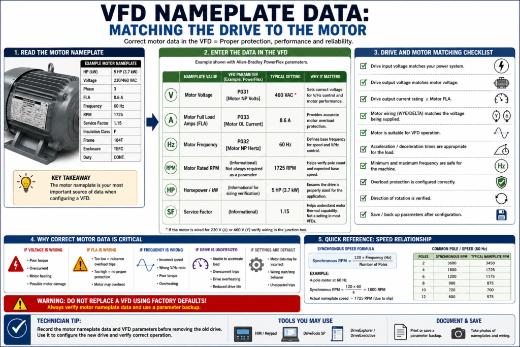
One of the most important steps when installing, replacing, or troubleshooting a Variable Frequency Drive is matching the VFD parameters to the actual motor nameplate.
A VFD does not automatically know the motor connected to it. The drive must be told key motor information such as voltage, full-load amps, frequency, speed, and overload settings. If these values are wrong, the motor may still run, but it may not run correctly, efficiently, or safely.
Incorrect motor data can cause:
- Motor overload faults
- Overcurrent faults
- Poor torque
- Motor heating
- Failed acceleration
- Nuisance trips
- Incorrect speed calculation
- Poor low-speed performance
- Wrong motor protection
This post explains how to read basic motor nameplate data and how that information is used when configuring a VFD.
The examples in this post may reference Allen-Bradley PowerFlex parameters, but the same concepts apply to most industrial VFDs.
Why Motor Nameplate Data Matters
A VFD controls the motor by adjusting voltage and frequency. To do that correctly, the drive needs to understand the motor it is controlling.
The motor nameplate provides the manufacturer-rated values that the VFD uses for:
Motor protection
Voltage-to-frequency control
Current limit behavior
Overload calculation
Speed reference setup
Torque performance
Drive-to-motor matching
On a PowerFlex 4, for example, the Basic Program Group includes parameters such as P031 Motor NP Volts, P032 Motor NP Hertz, and P033 Motor OL Current. The manual states that P031 should be set to the motor nameplate rated volts, P032 to the motor nameplate rated frequency, and P033 to the maximum allowable motor current.
That same idea exists in almost every VFD brand, even if the parameter numbers and names are different.
1. Motor Voltage
The motor voltage tells the drive what voltage the motor is designed to operate at.
Common industrial motor voltages include:
208 VAC
230 VAC
240 VAC
460 VAC
480 VAC
575 VAC
A motor nameplate may show more than one voltage, such as:
230/460 VThis means the motor can be wired for either voltage depending on the connection configuration.
Example
If the motor nameplate says:
Voltage: 460 VACThen the VFD motor voltage parameter should normally be set to:
460 VACFor a PowerFlex-style example:
P031 [Motor NP Volts] = 460The PowerFlex manual specifically describes P031 Motor NP Volts as the parameter set to the motor nameplate rated voltage.
Why This Matters
If the motor voltage is entered incorrectly:
| Incorrect Setup | Possible Result |
|---|---|
| Voltage set too low | Weak torque, poor performance |
| Voltage set too high | Motor heating, overcurrent, stress |
| Wrong dual-voltage wiring | Motor damage or immediate fault |
| Drive voltage does not match motor | Unsafe or failed installation |
A VFD replacement should never be completed without confirming both:
Drive input voltage rating
Motor nameplate voltage
2. Motor Full Load Amps / FLA
Motor full-load amps, often called FLA, is one of the most important nameplate values.
FLA means the amount of current the motor is expected to draw when operating at rated load.
The VFD uses this value for overload protection and current monitoring.
The glossary defines full load current or full load amps as the current drawn by a motor when operated at its full load torque.
Example
Motor nameplate:
FLA: 3.4 AVFD motor overload/current parameter:
Motor OL Current = 3.4 AFor a PowerFlex-style example:
P033 [Motor OL Current] = 3.4 AThe PowerFlex manual states that P033 Motor OL Current is set to the maximum allowable motor current and that the drive can fault on F7 Motor Overload if the value is exceeded by specified overload thresholds.
Why This Matters
If FLA is entered too high:
The motor may not be protected correctly.If FLA is entered too low:
The drive may trip on motor overload even when the motor is operating normally.This is a very common field issue after VFD replacement.
The drive may be new and healthy, but the motor overload setting may be wrong.
3. Motor Frequency
Most industrial AC motors are designed for either:
50 Hz
60 Hz
In the United States, most standard industrial motors are rated for 60 Hz.
The VFD must know the motor base frequency because frequency is directly related to speed and volts-per-hertz control.
For a PowerFlex-style example:
P032 [Motor NP Hertz] = 60 HzThe PowerFlex manual describes P032 Motor NP Hertz as the parameter set to the motor nameplate rated frequency.
Why This Matters
Motor frequency affects:
- Base speed
- Volts-per-hertz ratio
- Motor torque
- Overload behavior
- Speed scaling
- Maximum frequency decisions
The glossary defines constant volts per hertz as a method where the drive varies output voltage in direct proportion to frequency so the motor can produce full torque over the operating speed range.
4. Motor RPM
Motor RPM tells you the rated mechanical speed of the motor.
Common nameplate speeds include:
3450 RPM
1750 RPM
1725 RPM
1175 RPM
875 RPM
These values are usually slightly lower than synchronous speed because of slip.
For example, a 4-pole motor at 60 Hz has a synchronous speed of 1800 RPM, but the nameplate may show:
1725 RPMThat difference is normal.
The glossary defines slip as the difference between synchronous speed and rotor speed in an AC induction motor.
Speed Formula
A common speed formula is:
Synchronous RPM = (120 × Frequency) ÷ Number of PolesExample:
4-pole motor at 60 Hz

RPM = (120 × 60) ÷ 4
RPM = 1800 synchronous RPM
The motor may actually run around 1725 RPM because of slip.
Why RPM Matters
Motor RPM helps the technician understand:
- Motor pole count
- Base speed
- Required output frequency
- Application speed range
- Mechanical expectations
- Conveyor, pump, or fan performance
5. Horsepower / kW
The motor horsepower or kilowatt rating tells the mechanical power rating of the motor.
Common examples:
1 HP
2 HP
5 HP
10 HP
25 HP
50 HP
Or in metric:
0.75 kW
1.5 kW
3.7 kW
7.5 kW
15 kW
The VFD must be sized correctly for the motor and load. A drive should not be selected only by horsepower; current rating, voltage, duty, overload capacity, and application type also matter.
Technician Note
A 5 HP motor does not always mean every 5 HP drive is acceptable.
You must verify:
[ ] Drive input voltage
[ ] Drive output current rating
[ ] Motor FLA
[ ] Load type
[ ] Overload requirement
[ ] Ambient temperature
[ ] Enclosure rating
[ ] Duty cycle
[ ] Single-motor or multi-motor application
VFDs are available with voltage and current ratings to match most manufactured three-phase motors.
6. Service Factor
Service factor indicates how much continuous overload a motor may tolerate under specified conditions.
The glossary defines service factor as a number indicating the amount of continuous overload a component can withstand without serious degradation, commonly applied to AC induction motors.
A nameplate may show:
Service Factor: 1.15This does not mean the motor should always be operated above full load. It means the motor has some margin under defined conditions.
Important Point
Do not use service factor as an excuse to overload the motor continuously.
For VFD applications, motor cooling, speed range, load type, and enclosure type must be considered.
At low speed, a standard motor-mounted fan may not cool the motor as effectively.
7. Motor Connection: Wye / Delta or Dual Voltage
Many motors can be wired for different voltages.
Example:
230/460 VThis usually means the motor leads must be connected differently depending on the voltage.
A common mistake is replacing a drive or motor and forgetting to verify how the motor leads are configured.
Practical Example
If the motor is connected for 230 V but the drive is supplying 460 V:
Severe motor damage can occur.If the motor is connected for 460 V but the drive is supplying 230 V:
The motor may have weak torque and poor performance.Always verify the motor lead connection diagram on the motor nameplate or inside the motor junction box cover.
8. Insulation Class and Inverter Duty
Not all motors are equally suited for VFD operation.
When a motor is controlled by a VFD, the output waveform contains high-speed switching pulses. This can stress motor insulation, especially with long motor leads or older motors.
Important nameplate or specification terms:
Inverter Duty
Inverter Rated
Insulation Class
Temperature Rise
Duty Cycle
Technician Note
If the motor is old, runs hot, has long cable length, or fails repeatedly, check whether it is appropriate for VFD service.
Possible solutions may include:
[ ] Inverter-duty motor
[ ] Output reactor
[ ] dV/dt filter
[ ] Correct carrier frequency
[ ] Shorter motor leads
[ ] Better grounding/shielding
9. Load Type Matters
The motor nameplate tells you the motor capability, but the application tells you how hard the motor will be used.
Common load types:
| Load Type | Examples | VFD Consideration |
|---|---|---|
| Variable Torque | Fans, centrifugal pumps | Often easier on the drive at low speed |
| Constant Torque | Conveyors, mixers, positive displacement pumps | Requires torque across speed range |
| High Inertia | Centrifuges, large fans | Deceleration/braking may be critical |
| Overhauling Load | Hoists, downhill conveyors | Regeneration/braking may be required |
| Shock Load | Crushers, heavy indexing equipment | Higher overload capacity may be needed |
The glossary defines constant torque load as a mechanical device requiring approximately the same torque at all operating speeds, with starting torque requirements sometimes significantly greater than running torque.
10. Drive Rated Current vs Motor FLA
The VFD output current rating must be equal to or greater than what the motor and application require.
Do not only compare horsepower.
Compare:
Drive Output Amps ≥ Motor FLAAlso consider:
Overload capacity
Duty rating
Ambient temperature
Carrier frequency derating
Altitude derating
Single-phase input derating
The PowerFlex parameter section also includes A089 Current Limit, which sets the maximum output current allowed before current limiting occurs.
11. Minimum and Maximum Frequency
Nameplate data helps define the base operating point, but the technician must also understand the application speed range.
Common VFD parameters include:
Minimum Frequency
Maximum Frequency
Base Frequency
Maximum Voltage
For a PowerFlex-style example:
P034 [Minimum Freq]
P035 [Maximum Freq]
A088 [Maximum Voltage]
The PowerFlex manual states that P034 Minimum Frequency sets the lowest frequency the drive will continuously output, and P035 Maximum Frequency sets the highest frequency the drive will output.
Technician Warning
Do not assume it is always safe to run a motor above 60 Hz.
Running above base speed may reduce available torque and may exceed mechanical limits of:
Motor
Fan
Pump
Gearbox
Belt
Coupling
Driven machine
The glossary describes extended speed as operation above base speed, where motor torque commonly decreases as speed increases beyond base speed.
12. What Happens If the Drive and Motor Are Mismatched?
A mismatch between the VFD and motor can create many problems.
Wrong Motor Voltage
Possible symptoms:
Poor torque
Overcurrent
Motor heating
Motor damage
Drive fault
Wrong Motor FLA
Possible symptoms:
False overload trips
No overload protection
Motor runs hot
Nuisance faults
Wrong Motor Frequency
Possible symptoms:
Incorrect speed
Incorrect V/Hz curve
Torque problems
Overheating
Wrong Maximum Frequency
Possible symptoms:
Machine overspeed
Mechanical damage
Low torque above base speed
Unsafe operation
Wrong Drive Size
Possible symptoms:
Overcurrent trips
Unable to accelerate load
Drive overheating
Reduced drive life
Application failure
13. Example: Reading a Motor Nameplate
Suppose the motor nameplate shows:
HP: 1 HP
Voltage: 460 VAC
Phase: 3
FLA: 2.1 A
Frequency: 60 Hz
RPM: 1725
Service Factor: 1.15
Basic VFD setup should include:
| Nameplate Value | VFD Parameter Concept |
|---|---|
| 460 VAC | Motor Rated Voltage |
| 2.1 A | Motor Overload Current / Motor FLA |
| 60 Hz | Motor Rated Frequency |
| 1725 RPM | Motor Rated Speed |
| 3 Phase | Correct motor type/application |
| 1 HP | Drive sizing reference |
| SF 1.15 | Motor overload/application consideration |
PowerFlex-style example:
P031 Motor NP Volts = 460
P032 Motor NP Hertz = 60
P033 Motor OL Current = 2.1
P034 Minimum Frequency = application dependent
P035 Maximum Frequency = application dependent, often 60 Hz unless approved
14. Replacement Drive Checklist
When replacing a VFD, record this information before removing the old drive:
[ ] Drive catalog number
[ ] Drive input voltage
[ ] Drive output current rating
[ ] Motor horsepower / kW
[ ] Motor voltage
[ ] Motor FLA
[ ] Motor frequency
[ ] Motor RPM
[ ] Service factor
[ ] Motor wiring configuration
[ ] Start source
[ ] Speed reference
[ ] Minimum frequency
[ ] Maximum frequency
[ ] Accel time
[ ] Decel time
[ ] Stop mode
[ ] Digital input functions
[ ] Relay output functions
[ ] Analog input scaling
[ ] Communication settings
[ ] Fault history
[ ] Parameter backup
The PowerFlex manual explains that parameters can be viewed/edited using the integral keypad and can also be programmed using software such as DriveExplorer or DriveExecutive with a PC and serial converter module.
15. Technician Note: Do Not Trust Defaults
A new VFD from the box has factory default parameters.
Factory defaults are not the same as application settings.
A default drive may not know:
The correct motor FLA
The correct start source
The correct speed reference
The correct acceleration time
The correct deceleration time
The correct stop mode
The correct digital input assignments
The correct relay output assignments
The correct communication address
This is why parameter backups are so important.
16. Common Mistakes Technicians Should Avoid
Avoid these mistakes:
[ ] Replacing a VFD without recording motor nameplate data
[ ] Setting motor current based only on drive size
[ ] Ignoring dual-voltage motor wiring
[ ] Assuming a 460 V motor is wired correctly
[ ] Leaving motor overload current at default
[ ] Confusing input voltage with motor voltage
[ ] Running above base frequency without checking the machine
[ ] Ignoring motor cooling at low speed
[ ] Not checking service factor and duty cycle
[ ] Forgetting to save or print parameters
[ ] Not checking communication settings after replacement
[ ] Assuming every VFD brand uses the same parameter names
17. Simple Technician Explanation
A simple way to explain this topic is:
The motor nameplate tells the VFD what kind of motor it is controlling.
If the VFD has the wrong motor data, it may still run the motor, but it may not protect it correctly.
Or even shorter:
Correct nameplate data = correct motor protection and performance.Field Checklist: Matching a VFD to a Motor
Before starting or replacing a VFD, verify:
[ ] Motor voltage matches drive output voltage
[ ] Motor FLA is entered correctly
[ ] Motor frequency is entered correctly
[ ] Motor RPM is documented
[ ] Motor horsepower/kW is documented
[ ] Motor wiring matches the supplied voltage
[ ] Motor is suitable for VFD operation
[ ] Drive output amps are adequate
[ ] Minimum frequency is safe for the application
[ ] Maximum frequency is safe for the application
[ ] Accel/decel times are appropriate for the load
[ ] Overload protection is configured
[ ] Direction of rotation is verified
[ ] Parameter backup is saved
Final Thoughts
Matching a VFD to a motor is one of the most basic but most important tasks for an automation technician.
A VFD cannot protect or control a motor correctly if the motor data is wrong.
Before troubleshooting advanced problems, always verify the basics:
Motor voltage
Motor FLA
Motor frequency
Motor RPM
Drive output current rating
Motor wiring configuration
Application speed range
Many VFD problems are not caused by a bad drive. They are caused by incorrect setup, incorrect motor data, wrong wiring, or missing documentation.
A good technician does not only ask:
Why is the drive faulting?A good technician also asks:
Does this VFD actually know the motor it is controlling?