39. Industrial Ethernet Switches in Automation Systems (39 of 41)
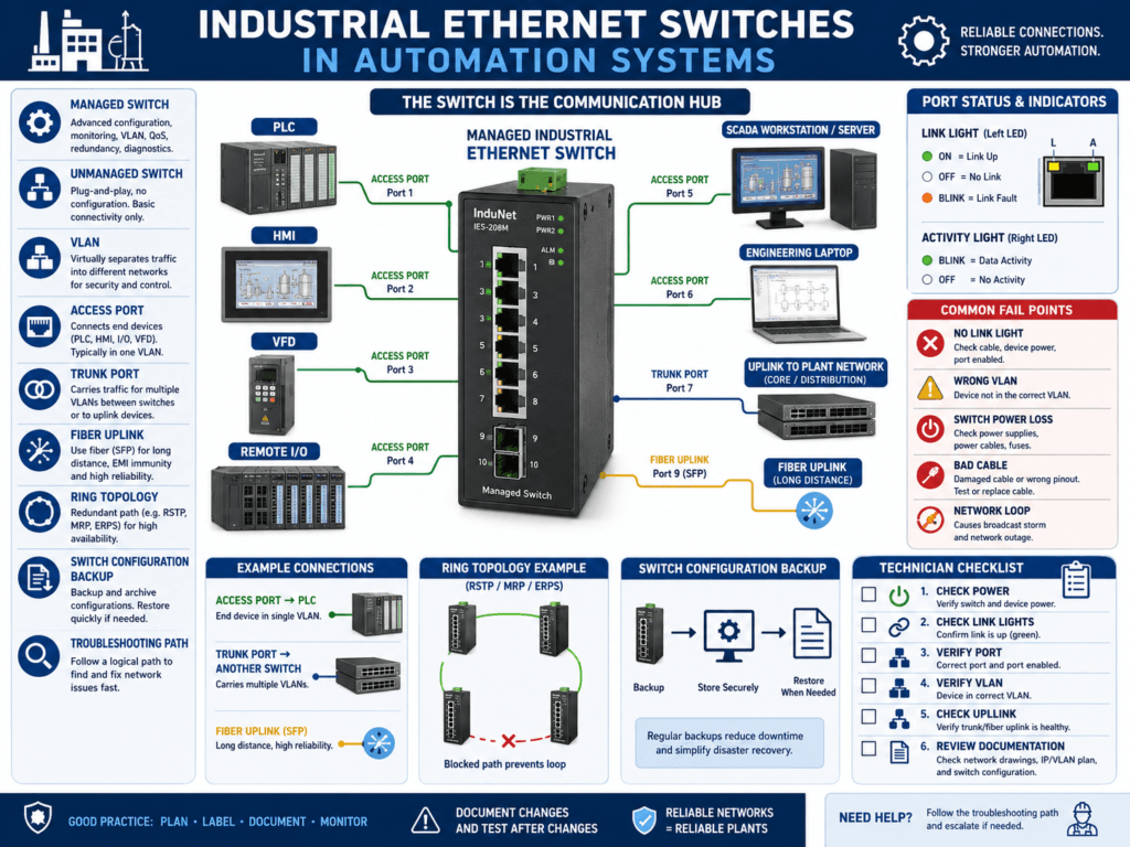
Industrial Ethernet switches are one of the most important parts of modern automation networks.
A switch connects devices such as:
PLC
HMI
VFD
Remote I/O
SCADA workstation
Vision camera
Robot controller
Servo drive
Barcode scanner
Engineering laptop
Historian server
A simple way to understand it:
An industrial Ethernet switch is the communication hub that allows automation devices to exchange data reliably.
If the switch, port, cable, VLAN, or configuration is wrong, the machine may lose communication even if the PLC program and field devices are correct.
That is why automation technicians must understand industrial switches.
1. What Does an Ethernet Switch Do?
An Ethernet switch connects multiple network devices together.
Basic concept:
PLC ↔ Switch ↔ HMI
PLC ↔ Switch ↔ VFD
PLC ↔ Switch ↔ Remote I/O
PLC ↔ Switch ↔ SCADA
The switch forwards network traffic between devices.
Example:
PLC sends command to VFD
     ↓
Switch forwards data to correct VFD port
     ↓
VFD receives command
     ↓
VFD sends status back through switch
     ↓
PLC receives feedback
The switch does not normally control the machine logic, but it supports the communication path that the machine depends on.
2. Why Switches Matter in Industrial Automation
In an industrial network, one switch may connect many critical devices.
If that switch loses power or has a port problem, you may see:
HMI communication fault
VFD communication fault
Remote I/O fault
SCADA data frozen
PLC-to-PLC message failure
Vision system offline
Robot communication loss
One switch problem can look like many device problems.
This is why technicians should always check the switch when several devices go offline at the same time.
3. Industrial Switch vs Office Switch
An industrial switch is designed for plant environments.
Industrial switches may support:
DIN rail mounting
24 VDC power
Wide temperature range
Vibration resistance
Redundant power inputs
Fiber ports
Ring topology
Managed configuration
Port diagnostics
VLANs
Quality of Service
Industrial protocol awareness
An office switch may work for simple testing, but it is not ideal for harsh industrial environments.
Industrial switches are built for reliability and maintainability in control panels.
4. Unmanaged Switch
An unmanaged switch is simple.
You connect devices, power it up, and it forwards traffic automatically.
Plug in devices
No configuration required
Traffic passes automatically
Advantages
Easy to install
Low cost
Simple replacement
Good for small isolated systems
Disadvantages
Limited diagnostics
No VLANs
No port security
No ring redundancy
No detailed port status
Harder to troubleshoot intermittent problems
Unmanaged switches are common in small machine networks.
But they give technicians very little information when something goes wrong.
5. Managed Switch
A managed switch can be configured, monitored, and backed up.
Managed switches may support:
Port status
Port enable / disable
VLANs
Ring redundancy
Port mirroring
Quality of Service
IGMP snooping
SNMP monitoring
User access control
Switch configuration backup
Traffic statistics
Fault logs
Advantages
Better troubleshooting
Better network control
Supports segmentation
Supports redundancy
Useful diagnostics
Better for larger OT networks
Disadvantages
Requires configuration
Wrong settings can break communication
Requires backup
Requires more technical knowledge
A managed switch is a powerful tool, but it must be documented and configured correctly.
6. Common Industrial Switch Brands
Common industrial switch families include:
Allen-Bradley Stratix
Hirschmann
Moxa
Phoenix Contact
Siemens Scalance
Cisco Industrial Ethernet
N-Tron
Red Lion
Weidmüller
Turck
In Allen-Bradley environments, Stratix switches are common because they integrate well with EtherNet/IP systems and Studio 5000 environments.
7. Switch Ports
Each Ethernet connection uses a switch port.
Example:
Port 1 = PLC
Port 2 = HMI
Port 3 = VFD
Port 4 = Remote I/O
Port 5 = SCADA uplink
Port 6 = Engineering laptop
Good documentation should show:
Device name
IP address
Switch name
Switch port number
Cable label
Panel location
VLAN if applicable
Example:
Filler PLC
IP: 192.168.10.10
Switch: SW-FILLER-01
Port: Gi1/1
Cable: CBL-PLC-01
Without switch port documentation, troubleshooting takes much longer.
8. Link and Activity LEDs
Switch port LEDs are extremely useful.
Common meanings:
Link LED ON = physical connection exists
Activity LED blinking = traffic is passing
No link LED = no physical connection
Fault LED = port or device issue
If a device is offline, check the switch port LED.
No Link Light
Possible causes:
Device powered off
Cable unplugged
Bad Ethernet cable
Bad RJ45 connector
Wrong switch port
Switch port disabled
Device Ethernet port damaged
Fiber transceiver issue
Link Light ON but No Communication
Possible causes:
Wrong IP address
Wrong subnet
Duplicate IP
Wrong VLAN
Firewall issue
PLC/HMI path wrong
Device configuration issue
Important concept:
A link light proves physical connection, not correct communication.
9. Switch Power
A switch must have stable power.
Many industrial switches use 24 VDC.
Some have redundant power inputs.
Check:
Power LED
24 VDC supply
Fuse or breaker
Redundant power input status
Grounding
Power supply health
If a switch loses power, every device connected through that switch may appear offline.
Example:
Remote I/O offline
VFD offline
HMI offline
SCADA data frozen
Root cause:
24 VDC power supply feeding switch failed.10. Fiber Ports and Uplinks
Industrial networks often use fiber for longer distances, high noise areas, or plant backbone connections.
Fiber may connect:
Main control room to production line
MCC room to packaging area
Plant network to remote panel
Ring network between switches
Fiber troubleshooting checks:
Fiber link LED
Correct SFP module
Correct fiber type
Clean fiber ends
Transmit/receive polarity
Fiber patch cable condition
Switch port status
Ring status
A fiber issue can take down multiple downstream devices.
11. VLANs
A VLAN is a logical network separation inside a switch.
Simple concept:
VLAN = Separate network group inside the same physical switchExample:
VLAN 10 = PLC / Machine Network
VLAN 20 = HMI / SCADA Network
VLAN 30 = Cameras
VLAN 40 = Vendor Access
VLANs help organize and segment traffic.
But VLANs must be configured correctly.
Wrong VLAN symptoms:
Device has link light but cannot communicate
Laptop cannot ping PLC
HMI cannot see PLC
SCADA cannot read tags
Important:
A cable plugged into the wrong VLAN port may look physically connected but still not communicate.
12. Trunk Ports and Access Ports
In managed switches, ports may be configured differently.
Access Port
An access port belongs to one VLAN.
Example:
Port 3 = VLAN 10 onlyUsed for devices like:
PLC
HMI
VFD
Remote I/O
Trunk Port
A trunk port carries multiple VLANs between switches.
Example:
Switch 1 ↔ Switch 2 trunk carries VLAN 10, 20, 30Used for:
Switch-to-switch uplinks
Router/firewall uplinks
Plant backbone connections
If a trunk is misconfigured, many devices can lose communication across networks.
13. Ring Topology and Redundancy
Some industrial networks use ring topology for redundancy.
Basic concept:
Switch 1 → Switch 2 → Switch 3 → Switch 4 → back to Switch 1If one cable breaks, communication may continue through the other direction if the ring protocol is working.
Common ring technologies include:
Device Level Ring
Rapid Spanning Tree Protocol
Media Redundancy Protocol
Vendor-specific ring protocols
Symptoms of ring issues:
Intermittent communication
Network storm
Multiple devices offline
Switch alarm active
Ring fault LED
Slow communication
A ring must be configured correctly. A wrong connection can create a network loop.
14. Network Loops
A network loop happens when traffic circulates endlessly through multiple switch paths.
This can overload the network.
Symptoms:
HMI freezes
Remote I/O faults
VFD communication drops
SCADA data stops updating
Switch LEDs blink rapidly
Network becomes slow or unstable
Causes:
Accidental cable loop
Wrong switch-to-switch connection
Ring not configured correctly
Spanning tree disabled
Unmanaged switch inserted incorrectly
Network loops can be serious in industrial systems.
15. Port Mirroring
Port mirroring copies traffic from one port to another for analysis.
Example:
Mirror PLC port traffic to laptop port
Use Wireshark to analyze communication
Used for advanced troubleshooting:
Packet loss
Broadcast storms
Protocol errors
Unexpected traffic
Communication timing issues
Most technicians may not use port mirroring every day, but it is a powerful managed-switch feature.
16. IGMP Snooping
IGMP snooping helps manage multicast traffic.
This is important in some EtherNet/IP systems.
Without proper multicast control, unnecessary traffic may flood many ports.
Possible symptoms:
Network slowdowns
Remote I/O instability
Drive communication issues
High switch traffic
Managed switches can help control multicast traffic when configured properly.
17. Switch Configuration Backup
Managed switches have configurations.
That means they need backups.
A switch configuration may include:
IP address
VLANs
Port settings
Ring settings
User accounts
Security settings
Uplink configuration
Port descriptions
SNMP settings
If a managed switch fails and you replace it without the correct configuration, communication may not work.
Important best practice:
Always backup managed switch configurations.18. Common Switch-Related Problems
Common issues include:
Switch lost power
Wrong cable plugged into wrong port
Bad port
Port disabled
Wrong VLAN
Duplicate IP issue blamed on switch
Fiber uplink failed
Ring fault
Network loop
Unmanaged switch added incorrectly
Switch config lost after replacement
Bad RJ45 connector
No switch documentation
These problems can cause major downtime.
19. Troubleshooting Method for Switch Problems
Use this method:
1. Identify which devices are offline.
2. Determine if one device or many devices are affected.
3. Check switch power.
4. Check device port link lights.
5. Check uplink port status.
6. Check cable and connector.
7. Check switch port assignment.
8. Verify VLAN if managed.
9. Check switch alarm/status LEDs.
10. Check ring or fiber status.
11. Check for recent changes.
12. Review switch configuration if needed.
This helps separate:
Device problem
Cable problem
Switch port problem
VLAN problem
Uplink problem
Configuration problem
20. Example: HMI Offline but PLC Running
Symptom
HMI shows communication error.
PLC is running normally.
Check
HMI power
HMI Ethernet link light
Switch port LED
HMI IP address
PLC IP address
Correct VLAN
HMI shortcut path
Possible root cause
HMI cable was moved to a switch port assigned to the wrong VLAN.The HMI had physical link, but it could not communicate with the PLC.
21. Example: Multiple Devices Offline
Symptom
VFD, Remote I/O, and HMI all offline.Check
Common switch power
Switch uplink
Fiber connection
24 VDC power to switch
Switch fault LED
Ring status
Possible root cause
Industrial switch lost 24 VDC power.This is not three device failures. It is one switch/power problem.
22. Best Practices
Use these best practices:
Label every Ethernet cable.
Label switch ports.
Document IP addresses.
Document VLANs.
Backup managed switch configuration.
Use industrial-rated switches.
Avoid unauthorized unmanaged switches.
Keep spare patch cables.
Check link lights first.
Document uplinks and fiber paths.
Secure unused ports based on plant policy.
Record changes after troubleshooting.
Good documentation can save hours during downtime.
23. Technician Checklist
When checking an industrial switch, verify:
Switch powered ON
Power LED normal
Fault LED clear
Device link lights ON
Activity LEDs normal
Correct cable connected
Correct switch port used
Port not disabled
Correct VLAN assigned
Uplink healthy
Fiber link healthy
Ring status normal
No obvious network loop
Switch configuration backed up
Port documentation updated
Final Thoughts
Industrial Ethernet switches are not just accessories.
They are critical parts of the automation system.
A PLC may be healthy.
A VFD may be healthy.
An HMI may be healthy.
But if the switch path is wrong, communication fails.
A strong automation technician understands the path:
Device → Cable → Switch Port → VLAN / Uplink → PLC / HMI / SCADAWhen communication fails, do not guess.
Check the switch.
Check the port.
Check the cable.
Check the VLAN.
Check the uplink.
Check the documentation.
The switch is the traffic controller of the industrial network. If it is misconfigured, powerless, or connected incorrectly, the whole machine can lose communication.
Understanding industrial switches makes you much stronger at troubleshooting PLC, HMI, VFD, Remote I/O, and SCADA communication issues.