36. Industrial Network Troubleshooting for Automation Technicians (36 of 41)
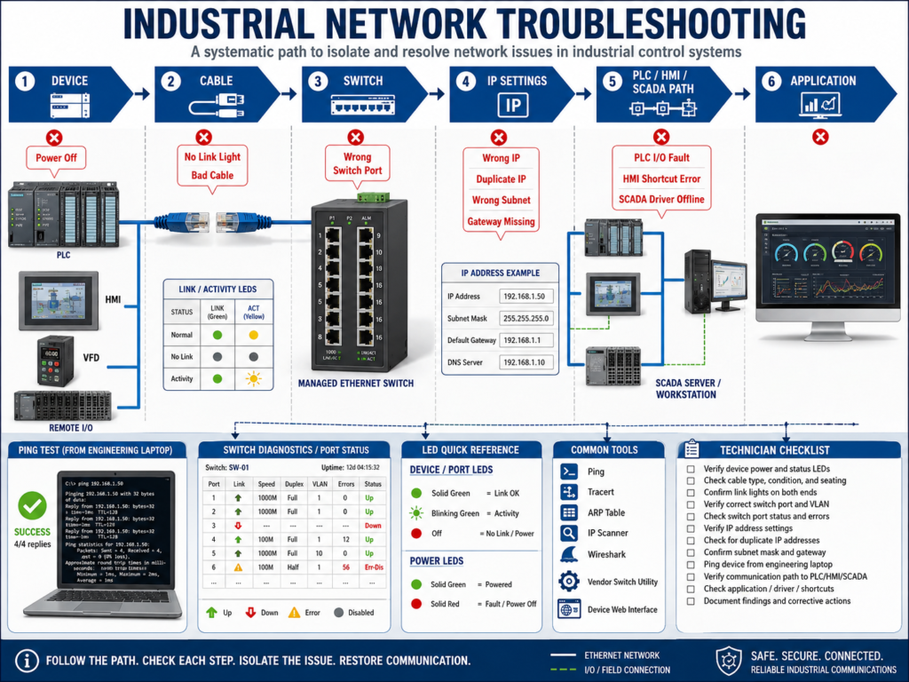
Modern industrial machines depend on communication.
A PLC may need to communicate with:
HMI
VFDs
Remote I/O
SCADA
Servo drives
Vision cameras
Barcode readers
Other PLCs
Industrial switches
Historian servers
When communication fails, the machine may stop, lose control, show faults, or display frozen data on the HMI.
But the most important rule is this:
Do not guess. Follow the communication path step by step.
A network fault can look like a PLC problem, an HMI problem, a VFD problem, or even a sensor problem.
The technician’s job is to isolate where the communication path is broken.
1. The Basic Communication Path
A simple industrial Ethernet path may look like this:
Device → Cable → Switch → Network Settings → PLC / HMI / SCADAFor example:
VFD
 ↓
Ethernet cable
 ↓
Managed switch
 ↓
PLC Ethernet port
 ↓
PLC I/O tree / communication path
If any part of that path fails, communication can be lost.
Common failure points:
Device powered off
Bad cable
Loose RJ45 connector
Bad switch port
Wrong IP address
Duplicate IP address
Wrong subnet mask
Wrong gateway
VLAN mismatch
PLC configuration mismatch
HMI shortcut error
SCADA driver issue
Firewall rule blocking traffic
2. First Question: What Exactly Is Not Communicating?
Before troubleshooting, define the problem clearly.
Ask:
Is the HMI not talking to the PLC?
Is the PLC not talking to a VFD?
Is remote I/O faulted?
Is SCADA not updating tags?
Is only one device offline?
Are multiple devices offline?
Is communication intermittent or completely lost?
This matters because one failed device and many failed devices point to different causes.
One Device Offline
Possible causes:
Device power issue
Bad cable to that device
Wrong IP address
Bad device port
Device fault
Wrong configuration
Many Devices Offline
Possible causes:
Switch power lost
Trunk/uplink cable failure
VLAN issue
PLC communication module fault
Fiber link issue
Network loop
Main switch failure
Power supply branch issue
3. Check Power First
Always start with power.
A device cannot communicate if it is not powered.
Check:
Is the device powered ON?
Are device LEDs active?
Is the 24 VDC supply healthy?
Is the breaker or fuse OK?
Is the switch powered?
Is the remote I/O rack powered?
Is the VFD powered?
Example:
Remote I/O fault on HMI
 ↓
Remote panel 24 VDC power supply failed
 ↓
All I/O modules in that panel are offline
This is not a network configuration problem.
It is a power problem.
4. Check Link Lights
Ethernet ports normally have link/activity LEDs.
Common meanings:
Link ON = physical connection detected
Activity blinking = data traffic present
No light = no physical link
If link light is OFF, check:
Cable connected?
Correct port?
Cable damaged?
RJ45 connector loose?
Device powered?
Switch port disabled?
Fiber media converter powered?
Wrong cable type?
Important:
If there is no link light, do not start changing PLC logic. Fix the physical connection first.
5. Check the Cable and Connector
Ethernet cable problems are very common in real plants.
Look for:
Loose RJ45 connector
Broken latch
Damaged cable jacket
Cable crushed in panel door
Cable pulled too tight
Oil or water contamination
Bad patch cable
Bad coupler
Wrong cable plugged into wrong port
Fiber patch damaged
Common symptoms:
Intermittent communication
Device drops out when panel door moves
HMI freezes randomly
VFD communication fault comes and goes
Remote I/O connection fault clears and returns
Technician tip:
If the problem changes when you move the cable, suspect cable or connector.6. Check the Switch Port
Industrial switches can provide important diagnostics.
Check:
Is the device connected to the expected switch port?
Is the port enabled?
Is the link up?
Are there port errors?
Are there CRC errors?
Is the port speed correct?
Is the port assigned to the correct VLAN?
Is the fiber uplink healthy?
On managed switches, port diagnostics can help you find:
Bad cables
Duplex mismatch
Traffic errors
Wrong VLAN
Disconnected devices
Network loops
High traffic
A managed switch is a powerful troubleshooting tool when configured and documented correctly.
7. Verify IP Address Settings
After physical checks, verify the network settings.
Check:
IP address
Subnet mask
Gateway
Device name
PLC I/O tree IP
HMI shortcut IP
SCADA driver path
Example:
PLC: 192.168.10.10
VFD expected: 192.168.10.30
Replacement VFD actual: 192.168.1.30
The VFD may power up and show link lights, but the PLC will not communicate because the IP address is wrong.
8. Check for Duplicate IP Address
Duplicate IP addresses can create confusing intermittent problems.
Symptoms:
Device connects and disconnects
Ping replies inconsistently
HMI sometimes communicates
PLC loses connection randomly
One device works only when another is unplugged
Common causes:
Replacement device installed with old/default IP
Laptop set to same IP as PLC
Two VFDs configured with same IP
BOOTP/DHCP assigned unexpected address
Copied configuration reused without changing IP
Best practice:
Keep an updated IP address list and verify before installing replacement devices.9. Use Ping Correctly
Ping is useful, but it has limits.
A successful ping means:
Basic network reachability exists.It does not prove:
PLC program is correct
HMI tag path is correct
EtherNet/IP I/O connection is healthy
VFD parameters are correct
SCADA driver is configured correctly
Example:
Laptop can ping VFD
but PLC still shows VFD communication fault
Possible causes:
Wrong module configuration in PLC
Electronic keying issue
Wrong assembly instance
VFD adapter mismatch
PLC connection path wrong
Ping is only one step.
10. HMI Communication Troubleshooting
If the HMI is not communicating with the PLC, check:
HMI power
Ethernet link lights
HMI IP address
PLC IP address
Subnet mask
Gateway if required
FactoryTalk Linx / RSLinx shortcut
Runtime application path
PLC controller name or shortcut target
Network cable and switch port
PLC online status
Symptoms:
HMI buttons do not work
Values show question marks
Screen data frozen
Alarm banner not updating
Mode changes not accepted
Troubleshooting path:
Press HMI button
Check if PLC request tag changes
If tag does not change, check HMI communication/path
If tag changes, check PLC logic
11. VFD Communication Troubleshooting
If the PLC loses communication with a VFD, check:
VFD powered
Ethernet adapter status
IP address
Subnet mask
PLC I/O tree configuration
Electronic keying
VFD firmware compatibility
Drive parameters
Connection status
Switch port
Cable
Duplicate IP
Common symptoms:
PLC major/minor I/O fault
Drive comm fault
Run command not received
Speed reference not updating
HMI shows drive offline
VFD status frozen
Important distinction:
VFD communication fault ≠ VFD motor faultA VFD can be healthy electrically but offline over the network.
12. Remote I/O Troubleshooting
Remote I/O faults can stop a machine quickly.
Check:
Remote I/O rack power
Adapter module status LEDs
Ethernet link lights
IP address
PLC I/O tree
Module keying
Slot configuration
Faulted module
Switch connection
Network cable
Symptoms:
Many inputs stop updating
Several outputs stop working
HMI shows remote rack offline
PLC shows I/O connection fault
Machine stops immediately
If many I/O points fail together, suspect the remote I/O adapter, power, or communication path before blaming individual sensors.
13. SCADA Communication Troubleshooting
If SCADA data is not updating, check:
SCADA server running
Driver connected
PLC reachable
OPC UA/driver status
Tag path correct
Historian running
Network route available
Firewall rules
Gateway settings
Time synchronization
Symptoms:
Trends stop updating
Alarm history missing
Dashboard frozen
Reports show no new data
SCADA tags bad quality
Important:
PLC and HMI may work locally while SCADA fails from another subnet.That may point to gateway, firewall, routing, or SCADA driver issues.
14. PLC-to-PLC Communication Troubleshooting
PLCs may exchange data using produced/consumed tags, MSG instructions, Modbus TCP, or other methods.
Check:
Both PLCs powered and in RUN mode
IP addresses correct
Network route available
Produced/consumed tag configuration
MSG instruction error code
Heartbeat bit changing
Timeout logic
Data size and type match
Controller names and paths correct
Good PLC-to-PLC communication should include:
Heartbeat
Communication healthy bit
Timeout fault
Data valid bit
Last update timestamp if needed
Without heartbeat logic, stale data may look valid.
15. Intermittent Communication Problems
Intermittent problems are often harder than complete failures.
Possible causes:
Loose cable
Bad connector
Duplicate IP
Switch port errors
Electrical noise
Bad grounding
Network loop
Failing device
Overloaded network
Fiber issue
Power dips
Troubleshooting tips:
Check switch port error counters
Trend communication faults
Wiggle-test suspect cable carefully when safe
Check if fault occurs with vibration
Check power supply stability
Check recent changes
Look for duplicate IP symptoms
Intermittent network problems require patience and evidence.
16. Common Real-Plant Scenarios
Scenario 1 — HMI Offline After PLC Replacement
Possible causes:
PLC IP changed
Controller name changed
HMI shortcut still points to old path
Runtime file not updated
Scenario 2 — VFD Offline After Replacement
Possible causes:
Replacement VFD has default IP
Drive parameters not restored
Ethernet adapter not configured
PLC electronic keying mismatch
Scenario 3 — Remote I/O Drops Randomly
Possible causes:
Loose Ethernet connector
Bad switch port
Power supply dip
Duplicate IP
Fiber issue
Network ring problem
Scenario 4 — SCADA Not Updating but HMI Works
Possible causes:
SCADA on different subnet
Gateway missing
Firewall blocking
SCADA driver stopped
Historian service issue
17. Troubleshooting Method: Follow the Layers
Use this field method:
1. Device power
2. Device status LEDs
3. Ethernet link light
4. Cable / connector
5. Switch port
6. IP address / subnet / gateway
7. Ping / reachability
8. PLC or HMI communication path
9. Device configuration
10. Application logic or tags
This keeps troubleshooting organized.
18. Common Mistakes
Mistake 1 — Blaming the PLC program first
Many network faults are physical or configuration-related.
Mistake 2 — Replacing devices without checking IP settings
A replacement device may still have a default IP.
Mistake 3 — Ignoring link lights
No link light usually means physical connection issue.
Mistake 4 — Not checking duplicate IP
Duplicate IP can create intermittent symptoms.
Mistake 5 — Not checking recent changes
Many faults happen after replacement, maintenance, or network changes.
Mistake 6 — No documentation
Without IP and switch port documentation, troubleshooting takes longer.
19. Best Practices
Use these practices:
Document IP addresses.
Label Ethernet cables.
Label switch ports.
Backup managed switch configurations.
Backup PLC and HMI programs.
Record device firmware and revision.
Use static IPs or controlled reservations.
Disable unused ports if required by plant policy.
Monitor switch diagnostics.
Keep spare Ethernet cables for testing.
Verify communication before returning to production.
Document root cause after repair.
20. Technician Checklist
When troubleshooting communication, verify:
Device powered ON
Status LEDs normal
Link light ON
Correct cable connected
Correct switch port
No visible connector damage
Correct IP address
Correct subnet mask
Correct gateway if needed
No duplicate IP
Device reachable by ping if allowed
PLC I/O tree healthy
HMI shortcut correct
SCADA driver connected
Remote I/O adapter healthy
VFD adapter healthy
Switch port healthy
Recent changes reviewed
Documentation updated
Final Thoughts
Industrial network troubleshooting is about following the path.
Do not guess.
Start with power.
Check link lights.
Check cables.
Check switch ports.
Verify IP settings.
Check for duplicate IP.
Test communication.
Verify PLC, HMI, VFD, remote I/O, or SCADA configuration.
The path is always:
Device → Cable → Switch → IP Settings → Communication Path → ApplicationA strong automation technician learns to separate:
Physical problem
Network configuration problem
PLC configuration problem
HMI/SCADA path problem
Device configuration problem
The first failed point in the communication path is where troubleshooting begins.
Understanding this method will make you much stronger when dealing with real plant communication faults.