34. Industrial Networks for Automation Technicians (34 of 41)
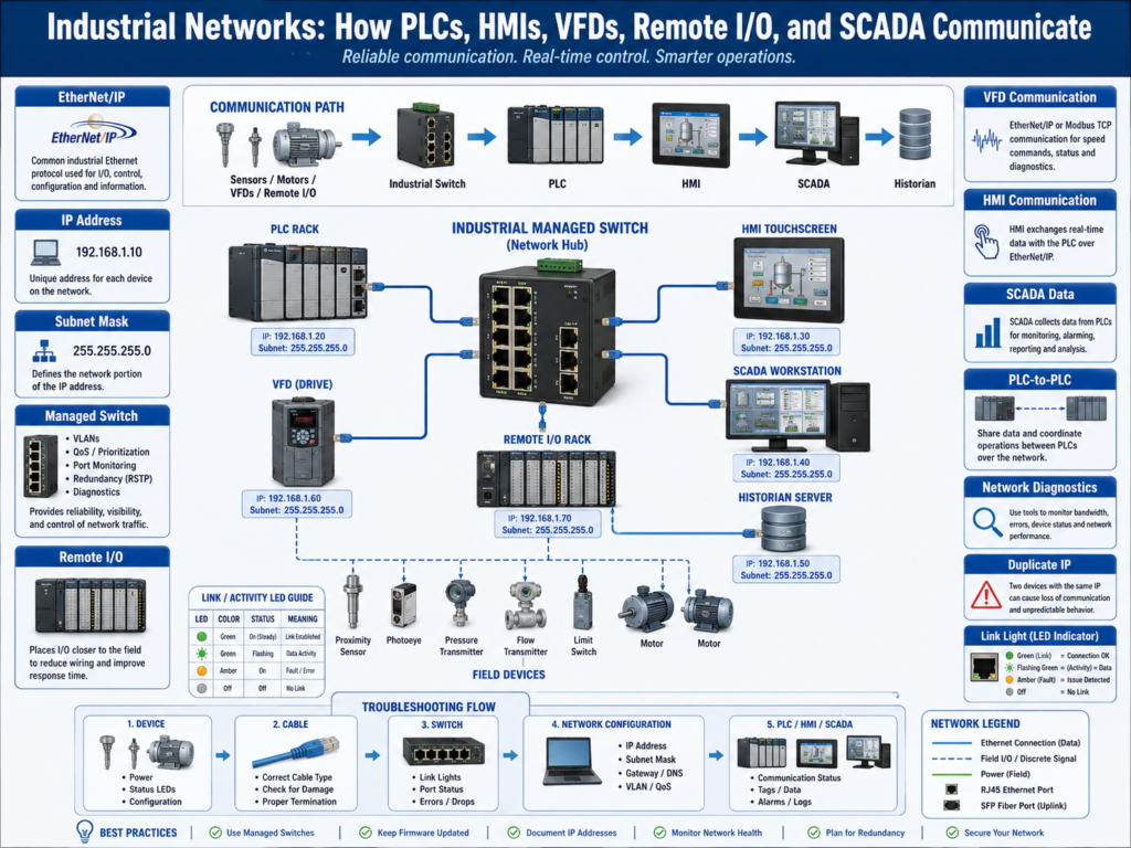
Modern industrial automation depends heavily on communication networks.
Years ago, many devices were connected mostly with hardwired signals.
Example:
PLC output → VFD start input
VFD relay output → PLC input
That still exists today, but modern systems often use industrial networks to exchange much more information.
Now a PLC may communicate with:
HMI
SCADA
Remote I/O
VFDs
Servo drives
Robots
Vision cameras
Barcode scanners
Other PLCs
Industrial switches
Safety controllers
Historians
A simple way to understand industrial networks:
Industrial networks allow automation devices to exchange control data, status, diagnostics, alarms, and production information.
1. Why Industrial Networks Matter
Industrial networks are important because they connect the entire automation system.
Without communication, each device is isolated.
With communication, devices can share:
Commands
Status
Fault codes
Analog values
Production counts
Recipes
Setpoints
Motor speed
Drive current
Remote I/O data
Alarm information
Diagnostics
Example:
PLC sends run command to VFD
VFD sends back running status, fault status, speed, and motor current
HMI displays drive status
SCADA logs motor current trend
This gives technicians much better visibility.
2. Hardwired vs Networked Control
Hardwired Control
Hardwired control uses physical wires for each signal.
Example:
PLC DO → VFD Start Input
VFD Fault Relay → PLC DI
PLC Analog Output → VFD Speed Reference
Advantages:
Simple to understand
Easy to meter
Good for basic signals
Less dependent on network configuration
Disadvantages:
More wiring
Limited diagnostics
More I/O points required
Harder to get detailed data
Networked Control
Networked control sends data through communication.
Example:
PLC ↔ EtherNet/IP ↔ VFDThe PLC may exchange:
Start command
Stop command
Speed reference
Fault reset
Running status
Fault code
Output frequency
Motor current
Drive ready status
Advantages:
Less hardwiring
More diagnostics
More data available
Easier integration with HMI and SCADA
Better device status visibility
Disadvantages:
Requires network configuration
IP addressing matters
Communication faults can stop equipment
More cybersecurity considerations
Troubleshooting requires network knowledge
3. Common Industrial Network Protocols
Industrial plants may use different protocols.
Common examples:
EtherNet/IP
PROFINET
Modbus TCP
DeviceNet
ControlNet
Profibus
Modbus RTU
IO-Link
EtherCAT
OPC UA
In Allen-Bradley systems, EtherNet/IP is very common.
In Siemens systems, PROFINET is very common.
Modbus TCP is common across many vendors.
OPC UA is commonly used for higher-level communication with SCADA, historians, and data platforms.
4. EtherNet/IP Basic Concept
EtherNet/IP is an industrial communication protocol commonly used with Allen-Bradley systems.
It allows PLCs to communicate with:
Remote I/O
VFDs
HMIs
Servo drives
Other PLCs
Robots
Vision systems
Industrial devices
Important:
EtherNet/IP is not the same as normal office Ethernet usage.It uses Ethernet hardware, but the protocol is designed for industrial automation data exchange.
Example:
CompactLogix PLC
     ↓
Industrial Ethernet Switch
     ↓
PowerFlex VFD
Remote I/O Rack
PanelView HMI
Vision Camera
5. IP Addressing Basics
Each Ethernet device needs an IP address.
Example:
PLC:        192.168.1.10
HMI:        192.168.1.20
VFD:        192.168.1.30
Remote I/O: 192.168.1.40
SCADA:      192.168.1.100
Devices must usually be in the correct subnet to communicate.
Example subnet:
IP Address: 192.168.1.10
Subnet Mask: 255.255.255.0
Network: 192.168.1.x
If one device has the wrong IP address or subnet, communication may fail.
Common symptoms:
HMI cannot see PLC
PLC loses remote I/O
VFD communication fault
Device shows connection timeout
SCADA tag values stop updating
6. MAC Address vs IP Address
A MAC address is the hardware address of a network device.
An IP address is the logical network address used for communication.
Simple difference:
MAC Address = physical device identity
IP Address = network location
Example:
MAC: 00:1D:9C:AA:10:22
IP:  192.168.1.30
Technicians commonly use IP addresses for troubleshooting communication.
MAC addresses may be useful when identifying devices, configuring BOOTP/DHCP, or checking switch tables.
7. Industrial Switches
Industrial Ethernet switches connect automation devices together.
Common devices connected to switches:
PLC
HMI
Remote I/O
VFD
Servo drive
Vision camera
Robot controller
SCADA computer
Engineering laptop
Industrial switches may support:
VLANs
Ring topology
Port diagnostics
Device-level ring
Quality of Service
Port mirroring
Managed configuration
Fiber connections
Redundancy
Examples:
Stratix switches
Hirschmann switches
Moxa switches
Phoenix Contact switches
Siemens Scalance switches
A switch is not just a cable splitter.
In industrial automation, it can be a critical part of the control system.
8. Unmanaged vs Managed Switches
Unmanaged Switch
An unmanaged switch is simple.
Plug devices in
Traffic passes automatically
Little or no configuration
Advantages:
Easy to use
Low cost
Simple replacement
Disadvantages:
Limited diagnostics
No VLANs
No port security
Limited troubleshooting visibility
Not ideal for complex OT networks
Managed Switch
A managed switch can be configured and monitored.
It may support:
VLANs
Port status
Ring redundancy
Port mirroring
Access control
Diagnostics
SNMP
Traffic statistics
Fiber port configuration
Advantages:
Better diagnostics
Better segmentation
Better network control
Useful for industrial troubleshooting
Supports more professional network design
Disadvantages:
Requires configuration
Wrong configuration can break communication
Needs backup of switch config
9. Remote I/O
Remote I/O allows input and output modules to be mounted away from the main PLC.
Example:
Sensors and solenoids near machine
     ↓
Remote I/O rack
     ↓
EtherNet/IP
     ↓
PLC
Why use remote I/O?
Less field wiring back to main panel
Cleaner machine layout
Faster installation
Easier expansion
Modular machine design
If remote I/O communication fails, the PLC may lose many inputs and outputs at once.
Symptoms:
Multiple sensors fail together
Several outputs stop responding
PLC shows I/O module fault
Machine faults immediately
HMI shows remote rack communication fault
10. VFD Communication
A VFD can be controlled through hardwired signals or through a network.
Networked VFD control may include:
Run command
Stop command
Speed reference
Fault reset
Direction command
Drive ready
Drive running
Faulted status
Fault code
Output frequency
Motor current
DC bus voltage
This is very powerful for diagnostics.
Example:
HMI displays:
VFD Fault Code = F005
Motor Current = 7.8 A
Output Frequency = 45.0 Hz
Drive Status = Running
That is much more useful than only seeing one fault relay input.
11. HMI and SCADA Communication
HMIs and SCADA systems usually communicate by reading and writing PLC tags.
Example:
HMI reads:
Machine_Running
Machine_Faulted
Tank_Level_Pct
Motor_Status

HMI writes:
Start_Request
Stop_Request
Reset_Request
Mode_Select
Setpoint_Value
Important:
The HMI should write requests. The PLC should validate and control outputs.
A communication issue may cause:
HMI values frozen
Buttons not working
Alarm screen not updating
Mode changes not accepted
SCADA trends missing data
12. PLC-to-PLC Communication
PLCs may communicate with each other.
Examples:
Line PLC sends production status to packaging PLC
Filler PLC sends bottle count to conveyor PLC
Safety status shared between cells
Upstream machine sends ready signal to downstream machine
Common methods:
Produced and consumed tags
MSG instructions
Modbus TCP registers
EtherNet/IP communication
Hardwired handshaking
A good PLC-to-PLC communication strategy should include:
Heartbeat
Status bits
Fault bits
Command bits
Data validation
Timeout detection
Without heartbeat or timeout logic, one PLC may believe stale data is still valid.
13. Network Topologies
Industrial networks may use different physical layouts.
Common topologies:
Star topology
Line topology
Ring topology
Redundant ring
Tree topology
Star Topology
Devices connect to a central switch.
PLC
HMI
VFDs
Remote I/O
all connect to one switch
Simple and common.
Ring Topology
Devices are connected in a loop with redundancy.
If one cable breaks, communication may continue through the other direction, depending on the ring protocol.
Common in industrial systems that need higher availability.
14. Common Network Problems
Industrial network problems can create many strange symptoms.
Common issues:
Wrong IP address
Duplicate IP address
Wrong subnet mask
Bad Ethernet cable
Loose RJ45 connector
Bad switch port
Fiber issue
Device powered off
Communication module fault
Wrong gateway
VLAN mismatch
Network loop
IP conflict
Firewall blocking traffic
Device firmware mismatch
Wrong PLC configuration
Symptoms may include:
HMI communication loss
Remote I/O fault
VFD communication timeout
SCADA data freeze
PLC-to-PLC message failure
Intermittent device dropouts
Network status LED flashing red
15. Basic Network Troubleshooting Method
Use a step-by-step method.
1. Identify which device is not communicating.
2. Check power to the device.
3. Check link lights on the Ethernet port.
4. Check cable and connector.
5. Check switch port status.
6. Verify IP address and subnet mask.
7. Ping the device if allowed.
8. Check PLC module status.
9. Check HMI or SCADA communication path.
10. Check alarms and diagnostics.
11. Check recent changes.
Do not immediately blame the PLC program.
Many communication problems are physical or configuration-related.
16. Network LEDs
Network LEDs are valuable troubleshooting tools.
Common indicators:
LINK
ACTIVITY
SPEED
EIP
NET
MOD
OK
FAULT
Example:
LINK ON = physical connection detected
ACTIVITY blinking = traffic is moving
NET red = network problem
MOD red = module/device fault
Always check the device manual because LED meanings vary by manufacturer.
17. Duplicate IP Address
A duplicate IP address happens when two devices use the same IP.
Symptoms:
Intermittent communication
One device drops when another powers up
HMI connects sometimes
PLC loses device randomly
Ping replies inconsistent
Duplicate IP problems can be very confusing.
Technician checks:
Review IP address list
Check device labels
Disconnect suspected device
Use switch diagnostics
Use ARP table if available
Check BOOTP/DHCP settings
Good documentation prevents this problem.
18. OT Network Documentation
A good industrial network should be documented.
Documentation should include:
Device name
IP address
Subnet mask
Gateway
MAC address if useful
Switch port
Panel location
Cable label
VLAN
Device role
Backup file location
Firmware version when important
Example:
Device: Filler PLC
IP: 192.168.10.10
Switch: Stratix-01
Port: Gi1/3
Panel: Filler Main Panel
Role: Main controller
This saves hours during troubleshooting.
19. Cybersecurity Basic Awareness
Industrial networks are part of OT cybersecurity.
Basic practices:
Do not connect unknown laptops to control networks
Do not install unauthorized routers
Disable unused switch ports when required
Document vendor remote access
Use proper user access control
Keep backups of PLC, HMI, and switch configs
Separate IT and OT networks
Use firewalls or controlled conduits where needed
A technician may not design the full cybersecurity system, but they should recognize risky network behavior.
20. Technician Checklist
When troubleshooting industrial networks, verify:
Device power
Ethernet link light
Correct cable
Correct switch port
Correct IP address
Correct subnet mask
No duplicate IP
PLC communication module healthy
HMI or SCADA path correct
Remote I/O module status
VFD communication status
Switch diagnostics
Fiber link if applicable
Recent changes
Network documentation
Backup availability
Final Thoughts
Industrial networks connect the automation system together.
They allow PLCs, HMIs, SCADA systems, VFDs, remote I/O, and smart devices to exchange data.
A strong automation technician does not need to be a full network engineer at first, but they must understand the basics:
IP addressing
Switches
Cables
Remote I/O
VFD communication
HMI communication
SCADA data flow
PLC-to-PLC communication
Network diagnostics
When communication fails, follow the path:
Device → Cable → Switch → Network Configuration → PLC / HMI / SCADADo not guess.
Check power.
Check link lights.
Check IP address.
Check the switch.
Check the PLC connection.
Check the HMI or SCADA path.
Check documentation.
Industrial networks are the communication backbone of modern automation systems.
Understanding this backbone gives automation technicians more confidence when troubleshooting real plant systems.