32. HMI Design & Alarm Management in Industrial Automation (32 of 41)
Categories :
Automation Technician Roadmap (1 of 41)
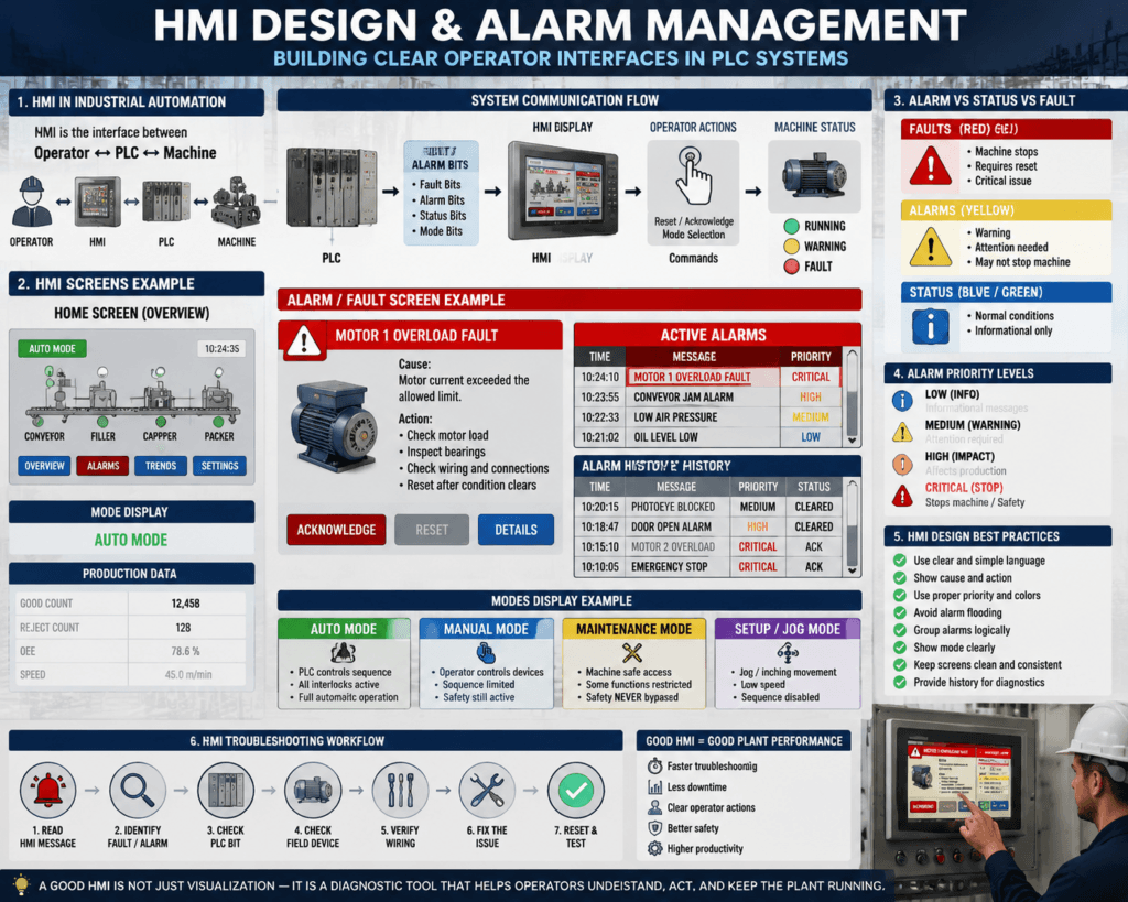
In industrial automation, the PLC does NOT operate alone.
The real interaction happens through the HMI (Human Machine Interface).
And a bad HMI design can turn a simple machine into:
A confusing system
A troubleshooting nightmare
A production bottleneck
A good HMI does the opposite:
It guides the operator
It reduces downtime
It shows root cause clearly
It simplifies troubleshooting
1. What Is an HMI in Industrial Automation?
An HMI is the interface between:
Operator ↔ PLC ↔ MachineIt displays:
Machine status
Faults
Alarms
Modes (Auto/Manual/etc.)
Production data
Diagnostics
And allows:
Start / Stop commands
Mode selection
Reset faults
Manual control (if allowed)
2. Why HMI Design Matters So Much
Bad HMI:
“Fault 103”
No explanation
No action
Operator guesses
Good HMI:
Motor Overload Fault
Cause: High current detected
Action: Check load, motor, wiring, reset after clearing
3. Alarm vs Status vs Fault on HMI
A professional HMI separates clearly:
🔴 Faults
Machine stops
Requires reset
Critical issue
🟡 Alarms
Warning or attention needed
May or may not stop machine
🔵 Status
Normal conditions
Informational only
4. Alarm Management Structure
A proper alarm system includes:
Active alarms
Acknowledged alarms
Alarm history
Timestamp
Priority level
Cause description
Action message
5. Alarm Priority Levels
Industrial systems use priority:
| Level | Meaning |
|---|---|
| Low | Info |
| Medium | Warning |
| High | Production impact |
| Critical | Stop machine |
Example:
Low → Maintenance reminder
High → Conveyor jam
Critical → Safety fault
6. Alarm Example (Real Plant)
Condition:
Photoeye blocked too longHMI output:
CONVEYOR JAM ALARM
- Sensor blocked > 5 sec
- Check product blockage
- Check photoeye alignment
7. Fault Display Strategy
Faults should ALWAYS show:
What happened
Where it happened
Why it happened
How to fix it
Example:
MOTOR 1 OVERLOAD FAULT
Cause: Current exceeded limit
Check: Load, bearings, wiring
Reset allowed after condition clears
8. HMI Mode Display (Critical)
HMI must always show current mode:
AUTO MODE
MANUAL MODE
MAINTENANCE MODE
SETUP MODE
Why?
Because many issues come from:
Operator in wrong mode
Technician in manual mode
Auto sequence blocked
9. Alarm & Fault Logic Connection
HMI depends on PLC tags:
Fault bits → red screen
Alarm bits → yellow banner
Status bits → normal display
Mode bits → control permissions
Example:
MTR1_Fault = 1 → show fault screen
MTR1_Alarm = 1 → show warning banner
MTR1_Run = 1 → show running status
10. Alarm Latching vs Non-Latching
Latching alarm:
Stays active until acknowledgedNon-latching alarm:
Clears automatically when condition disappearsBest practice:
Faults = latched
Critical alarms = latched
Warnings = sometimes non-latched
11. Alarm Flooding Problem
Bad design causes:
Too many alarms at once
Operator ignores system
Important alarms missed
Solution:
Priorities
Grouping alarms
Suppress duplicates
Logical filtering
12. HMI Design Best Practices
Use clear language
Avoid codes only (like Fault 101)
Show root cause
Show action steps
Group alarms logically
Use color coding correctly
Keep screens simple
Avoid overload of information
13. Example: Good vs Bad HMI
❌ Bad:
FAULT 47✅ Good:
Conveyor Motor Overload Fault
Cause: Excess load or jam
Action: Inspect conveyor and reset after clearing issue
14. HMI & PLC Communication Flow
Sensor → PLC Logic → Fault/Alarm Bits → HMI Display → Operator Action → Reset → PLC15. Troubleshooting Using HMI
Technician workflow:
1. Read HMI message
2. Identify fault/alarm type
3. Check PLC bit
4. Check field device
5. Verify wiring
6. Fix issue
7. Reset system
Final Thoughts
A PLC system without good HMI design is incomplete.
Because:
PLC controls the machine
HMI explains the machine
If the HMI is unclear:
- operators guess
- downtime increases
- troubleshooting becomes slower
A good HMI is not just visualization — it is a diagnostic tool.