19. Bonus Post — VFD Bypass, Line Reactors, Output Reactors, dV/dt Filters, and When to Use Them (19 of 19)
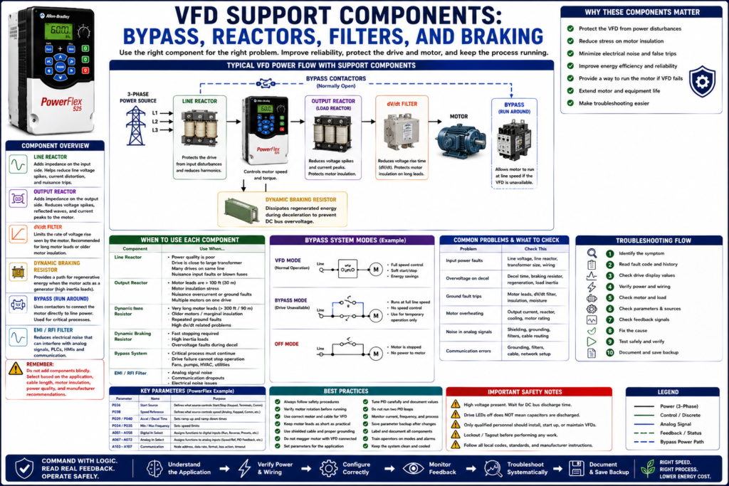
Introduction
A Variable Frequency Drive is the main device that controls motor speed, but many real industrial installations include additional components around the drive.
These components may include:
VFD bypass contactors
Line reactors
Load reactors / output reactors
dV/dt filters
EMI/RFI filters
Dynamic braking resistors
Fuses and circuit breakers
Disconnect switches
Shielded motor cable
These devices are not installed randomly. Each one solves a specific problem.
A good automation technician should know what these components do, where they are installed, and why they may be required.
This post explains the most common VFD support components and when they are typically used.
1. Why VFD Accessories Matter
A VFD can be correctly programmed but still have problems if the system around it is not designed correctly.
Common problems that may require additional components include:
Input voltage spikes
Power quality issues
Long motor cable runs
Motor insulation stress
Ground fault trips
Electrical noise
Communication problems
Analog signal noise
DC bus overvoltage during deceleration
Need to run motor if the VFD fails
The goal of these accessories is to improve:
Reliability
Motor protection
Drive protection
Noise reduction
Power quality
System uptime
Troubleshooting clarity
2. VFD Bypass: What It Is
A VFD bypass allows the motor to run without the VFD.
In a bypass system, the motor can be connected either:
Through the VFDor
Directly across the line using contactorsA simple concept:
Normal Mode:
Power → VFD → Motor

Bypass Mode:
Power → Bypass Contactor → Motor
Bypass is commonly used in applications where keeping the motor running is critical, even if speed control is lost.
3. When Is a VFD Bypass Used?
A bypass may be used when the process cannot easily stop.
Common applications:
HVAC supply fans
Exhaust fans
Cooling tower fans
Process pumps
Water pumps
Critical ventilation systems
Building systems
Some utility systems
Example:
If a VFD fails on a critical exhaust fan, bypass may allow the fan to run at full speed until the drive is repaired or replaced.4. Important Bypass Warning
A bypass is not the same as VFD control.
When a motor runs in bypass:
The motor runs at full line speed.
Acceleration ramp is lost.
Deceleration ramp is lost.
Speed control is lost.
VFD overload protection may be bypassed.
PLC/HMI feedback may change.
The motor starter/bypass protection must be correct.
This is critical.
A bypass can help keep a process running, but it changes how the motor behaves.
5. VFD Mode vs Bypass Mode
| Feature | VFD Mode | Bypass Mode |
|---|---|---|
| Motor speed | Variable | Fixed full speed |
| Acceleration | Controlled ramp | Across-the-line start |
| Deceleration | Controlled or coast | Usually coast |
| Energy savings | Yes | No |
| Soft start | Yes | No |
| PLC speed control | Yes | No |
| Fault protection | Drive-based | Bypass starter/protection |
| Best use | Normal operation | Emergency/temporary operation |
6. Bypass Control Considerations
A professional bypass system should clearly show:
VFD Mode
Bypass Mode
Off Mode
VFD Fault
Bypass Running
Motor Running
Overload Trip
Hand/Auto status
The PLC/HMI should not simply show “VFD Running” when the motor is actually running in bypass.
Better tags:
Motor_Running_FB
VFD_Mode_Active
Bypass_Mode_Active
VFD_Running_FB
Bypass_Running_FB
Bypass_Overload_Trip
7. Line Reactor: What It Is
A line reactor is an inductive device installed on the input side of the VFD.
Location:
Power Source → Line Reactor → VFD → MotorIts purpose is to add impedance between the power supply and the drive.
This can help protect the VFD from input power disturbances.
8. When to Use a Line Reactor
A line reactor may be used when:
The drive is close to a large transformer.
Input voltage has spikes or transients.
There are frequent power disturbances.
There are many drives on the same line.
Power factor correction capacitors are nearby.
Input fuses blow repeatedly.
The drive trips on input-related faults.
The installation has low line impedance.
A line reactor may help reduce:
Input current peaks
Voltage spikes
Nuisance trips
Stress on input rectifier
Power quality issues
9. Line Reactor Troubleshooting Clues
Consider the input side if you see:
Power Loss faults
Undervoltage faults
Input fuse failures
Drive trips when other equipment starts
Nuisance faults during power disturbances
Rectifier/input section failures
Field checks:
Measure line voltage.
Check phase balance.
Check voltage during startup.
Check transformer size.
Check power quality.
Check for loose terminals.
Check if multiple drives fault at the same time.
10. Output Reactor / Load Reactor: What It Is
An output reactor, also called a load reactor, is installed between the VFD output and the motor.
Location:
Power Source → VFD → Output Reactor → MotorIts purpose is to reduce stress on the motor and drive output caused by the VFD’s PWM waveform.
11. When to Use an Output Reactor
An output reactor may be used when:
Motor leads are long.
Motor insulation is older.
The motor is not inverter-duty.
There are nuisance overcurrent or ground fault trips.
The motor is noisy.
The system has reflected wave issues.
Multiple motors are connected to one VFD.
The environment has high electrical noise.
Output reactors can help reduce:
Voltage spikes at motor terminals
Motor insulation stress
Motor heating
Audible noise
Output current peaks
Nuisance drive trips
12. dV/dt Filter: What It Is
A dV/dt filter is installed on the output side of the VFD.
Location:
VFD → dV/dt Filter → MotorThe term dV/dt refers to how fast voltage changes over time.
VFD output pulses switch very quickly. This fast switching can stress motor insulation, especially on long cable runs.
A dV/dt filter reduces the steep voltage rise time of the VFD output waveform.
13. Output Reactor vs dV/dt Filter
| Device | Main Purpose | Typical Use |
|---|---|---|
| Output Reactor | Adds impedance and reduces output stress | General protection, moderate cable lengths |
| dV/dt Filter | Reduces fast voltage rise time | Long cable runs, motor insulation protection |
| Sine Wave Filter | Makes output waveform closer to sine wave | Very long leads, special motors, sensitive applications |
Simple explanation:
Output reactor = basic output protection.
dV/dt filter = stronger motor insulation protection.
Sine wave filter = most advanced output waveform filtering.
14. When Long Motor Leads Become a Problem
Long motor cable runs can create issues because of the VFD’s high-speed switching output.
Possible symptoms:
Ground fault trips
Overcurrent trips
Motor insulation failure
Motor heating
Bearing problems
Electrical noise
Communication interference
Analog signal noise
Premature motor failure
Possible solutions:
Use VFD-rated motor cable.
Shorten motor leads if possible.
Install output reactor.
Install dV/dt filter.
Use inverter-duty motor.
Verify grounding and shield termination.
Check carrier frequency.
Follow manufacturer cable length limits.
15. EMI / RFI Filters
EMI/RFI filters reduce electrical noise.
EMI means:
Electromagnetic InterferenceRFI means:
Radio Frequency InterferenceVFDs can generate noise because they switch power devices very quickly.
This noise can affect:
Analog signals
Load cells
Pressure transmitters
Flow meters
Encoders
PLC inputs
Ethernet communication
HMI communication
Nearby instrumentation
16. When to Consider EMI/RFI Filtering
Consider noise mitigation when you see:
Analog signal jumping
4–20 mA signal unstable
0–10 V speed reference noisy
PLC inputs flickering
Communication dropouts
Encoder feedback problems
HMI communication issues
Nearby instruments behaving strangely
But do not install filters blindly.
First check:
Grounding
Shielding
Cable routing
Separation between power and control wiring
Shield termination
Panel bonding
Motor cable type
Carrier frequency
Noise problems are often installation problems.
17. Dynamic Braking Resistor
A dynamic braking resistor is used when the motor/load regenerates energy back into the VFD during deceleration.
Location concept:
Motor regenerates energy → DC Bus voltage rises → Brake circuit sends energy to resistor → Resistor dissipates heatUsed when:
High inertia load must stop quickly.
Drive trips on overvoltage during deceleration.
Conveyor load pushes the motor.
Fan or centrifuge needs fast stopping.
Hoist or overhauling load requires braking design.
18. Dynamic Braking vs Coast Stop
If a drive trips on overvoltage during stopping, there are two common approaches:
Increase deceleration time or coast stopor
Use dynamic braking| Method | What It Does | Best For |
|---|---|---|
| Increase Decel Time | Slows the stopping ramp | Simple loads, less braking demand |
| Coast Stop | Lets motor freewheel | High-inertia loads where stop time is not critical |
| Dynamic Braking | Dissipates regenerated energy | Fast stops, high inertia, frequent decel |
19. Fuses, Breakers, and Disconnects
A VFD installation still needs proper upstream protection.
Common devices:
Disconnect switch
Circuit breaker
Fuses
Branch circuit protection
Motor circuit protection
Overload protection, depending on bypass design
Important reminder:
The VFD does not automatically replace all required branch circuit protection.Always follow:
Manufacturer manual
Electrical code
Plant standard
Short-circuit current rating requirements
Proper wire sizing
Proper fuse/breaker selection
20. Shielded Motor Cable
Shielded motor cable is often recommended for VFD applications.
Benefits:
Reduces electrical noise
Improves EMC performance
Helps protect nearby signal wiring
Provides better grounding path when installed correctly
Improves reliability in sensitive applications
Important:
The shield must be terminated correctly.
Poor shield termination can make noise problems worse.
Always follow the drive and cable manufacturer instructions.
21. Carrier Frequency Consideration
Carrier frequency affects how the VFD switches its output devices.
Higher carrier frequency may reduce audible motor noise, but it can increase drive heating and may require derating.
Lower carrier frequency may be easier on the drive but may make the motor sound louder.
Technician note:
Do not change carrier frequency only because the motor sounds noisy.
Check the manual, drive temperature, motor lead length, and application requirements.
22. Quick Selection Guide
| Problem / Requirement | Component to Consider |
|---|---|
| Input voltage spikes | Line reactor |
| Large transformer close to drive | Line reactor |
| Long motor leads | Output reactor or dV/dt filter |
| Motor insulation stress | dV/dt filter |
| Very sensitive output waveform needs | Sine wave filter |
| Analog signal noise | Shielding, grounding, EMI/RFI filtering |
| Communication dropouts | Grounding, shielding, cable routing, filters |
| Overvoltage during decel | Dynamic braking resistor or longer decel |
| Need to run motor if VFD fails | Bypass system |
| High electrical noise | Shielded cable, filters, proper bonding |
23. Troubleshooting by Component
Line Reactor Area
Check when:
Drive has input-related faults.
Multiple drives fault during plant power events.
Input fuses fail.
Power quality is unstable.
Output Reactor / dV/dt Area
Check when:
Motor leads are long.
Motor insulation fails.
Drive trips on ground fault or overcurrent.
Motor cable creates noise problems.
Bypass Area
Check when:
Motor runs in bypass but not in VFD mode.
VFD mode runs but bypass does not.
PLC/HMI status is confusing.
Bypass overload trips.
Mode selector does not behave correctly.
Dynamic Braking Area
Check when:
Drive faults on overvoltage during deceleration.
Brake resistor is overheating.
Fast stopping is required.
Decel time is too short for the load.
24. Common Mistakes Technicians Should Avoid
[ ] Assuming every VFD needs every accessory.
[ ] Installing filters without fixing grounding problems.
[ ] Using bypass without understanding full-speed operation.
[ ] Forgetting overload protection in bypass mode.
[ ] Using a VFD output contactor as normal start/stop control.
[ ] Ignoring long motor lead limits.
[ ] Changing carrier frequency without checking derating.
[ ] Installing a braking resistor without enabling/checking parameters.
[ ] Not documenting bypass logic.
[ ] Not updating drawings after adding filters or reactors.
25. Technician Checklist
[ ] Identify the application: fan, pump, conveyor, mixer, hoist, etc.
[ ] Check if bypass is required or installed.
[ ] Verify input power quality.
[ ] Check if a line reactor is installed.
[ ] Check motor lead length.
[ ] Check if output reactor or dV/dt filter is required.
[ ] Verify motor is inverter-duty when needed.
[ ] Check grounding and bonding.
[ ] Check shielded cable and shield termination.
[ ] Check for analog or communication noise.
[ ] Check if dynamic braking is installed.
[ ] Verify braking parameters.
[ ] Verify bypass overload protection.
[ ] Verify PLC/HMI feedback for VFD mode and bypass mode.
[ ] Update drawings and documentation.
Simple Technician Explanation
A simple way to explain this topic is:
VFD accessories solve problems around the drive.
Line reactors protect the input side.
Output reactors and dV/dt filters protect the motor side.
Braking resistors manage stopping energy.
Bypass keeps critical motors running if the drive cannot be used.
Or even shorter:
Line side protection.
Load side protection.
Noise control.
Braking control.
Backup running mode.
Final Thoughts
A VFD is part of a larger motor control system. The drive itself is important, but the components around it can be just as important for reliability.
A good technician does not only look at the VFD parameters. A good technician also looks at:
Input power quality
Motor cable length
Grounding
Shielding
Cooling
Bypass logic
Braking requirements
Noise-sensitive signals
Application requirements
The best mindset is:
Use accessories to solve real application problems.
Do not add them blindly.
Always follow the manual.
Verify the wiring.
Document the system.
That is how VFD installations become more reliable and easier to troubleshoot.